Digital diversity dilemma
Applied Radiology — Vol. 34 , Issue 5 , pp. 34 -45
DOI: 10.37549/AR1336
Published: May 1, 2005
Categories
Recent advances in semiconductor manufacturing technology may be the “genie in the bottle” that every radiologist wishes for: Electronically readable X-ray detectors that can provide both excellent image quality and the capability of very rapid access to, enhancement of, and distribution of, the digital image output. Coupled with robust computer technology, digital radiography (DR) devices provide integrated direct readout of the image data and eliminate the time and equipment associated with film processing and development.
In many cases, the inherent efficiencies of digital technologies can lower the radiation dose. Patient throughput can be greatly increased; in fact, the time it takes to reposition the patient for a second image can actually exceed the cycle time of the device, which can be only a few seconds. There are many different methods used to capture and convert X-rays into electronic signals for immediate display, and the enviable digital dilemma facing radiologists now is to understand the many different detector and readout systems available through this emerging technology to enable an educated choice for their particular applications.
Flat-panel thin-film transistor arrays
To take full advantage of the development of large-area X-ray detectors, DR systems need integrated large-area readout mechanisms with sophisticated, but miniaturized, electronic circuitry to capture the electronic charge image data. The mechanism must be capable of low noise, wide dynamic range, and fast response. Thin-film transistor arrays make use of electronic microfabrication techniques to position electrodes for pixel charge collection and readout mechanisms in layers immediately adjacent to the site of the photon interactions, all within a protective enclosure, complete with cabling for computer connection.1 Bias voltages channel the charges from the surface of the photodetector to the nearest collector electrode in the transistor array. Pixel separation is assured by electronic field shaping within the photodetector, which preserves spatial resolution and can produce a very high fill factor (approaching 100%). The electronic charge information is converted from analog to digital and processed by a computer for display on a monitor and storage in a DICOM-compliant form.
Components used in direct readout digital devices
Amorphous selenium
A photoconductor is a type of semiconductor that is an insulator under conditions of darkness but becomes a conductor when illuminated. The light-sensitive electrical properties of photoconductors make them useful in various devices, such as infrared detectors and video cameras. When X-rays strike a photoconductor, such as selenium, the energy of the incoming photons excites the low-energy selenium valance electrons, causing them to move into a higher energy state called the conduction band. The “holes” formed after the electrons are released can be thought of as positive charges that attract neighboring negatively charged electrons.2 As electrons move into these holes, they leave new holes. These electron-hole pairs function as charge carriers. If an electric field is formed by positively charging one surface of the photoconductor, the released electrons and the holes will move along the applied field toward opposite surfaces of the photoconductor, where the electrons will cancel the positive surface charges (Figure 1). The resulting variations in the surface charge correspond to the incident pattern of the X-rays and faithfully reproduce the original X-ray image. This method of transforming X-ray energy directly into an electric charge is called direct conversion.
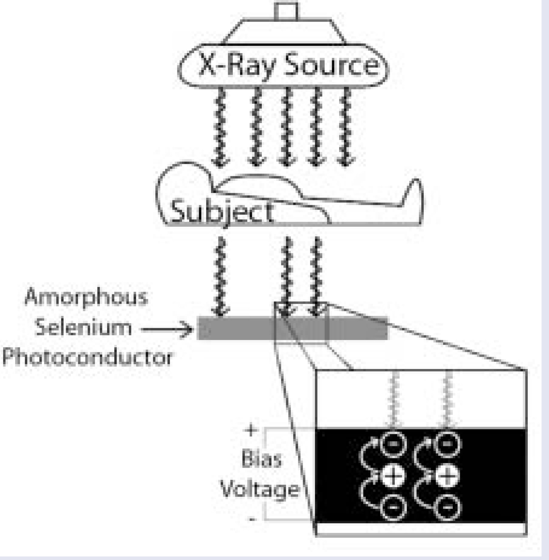
The photoconductive properties of selenium make it particularly well suited for use in digital radiography. It has a very low dark or leakage current, it forms approximately 1000 electron-hole pairs per 50 keV X-ray beam at an electric field of 10 volts per micron, and it has good attenuation of X-rays (~50% attenuation of a 50 keV beam with 365 microns of selenium; 50% attenuation of a 20 keV beam with 30 microns of selenium).2 Advances in the manufacture of semiconductor materials has made it possible to make large surface area plates of selenium by evaporation of its amorphous form instead of earlier methods that relied on growing selenium crystals. This has made production of flat-panel sele-nium-based electronic X-ray detectors much more economical.
Amorphous silicon
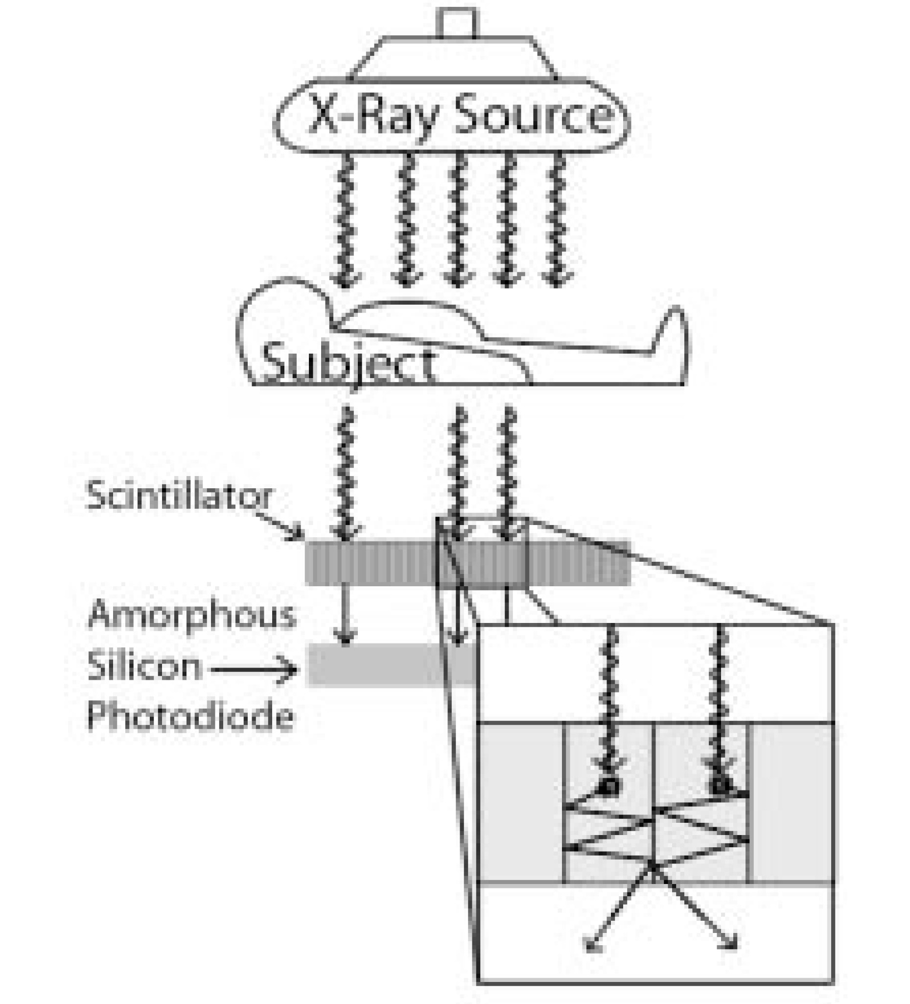
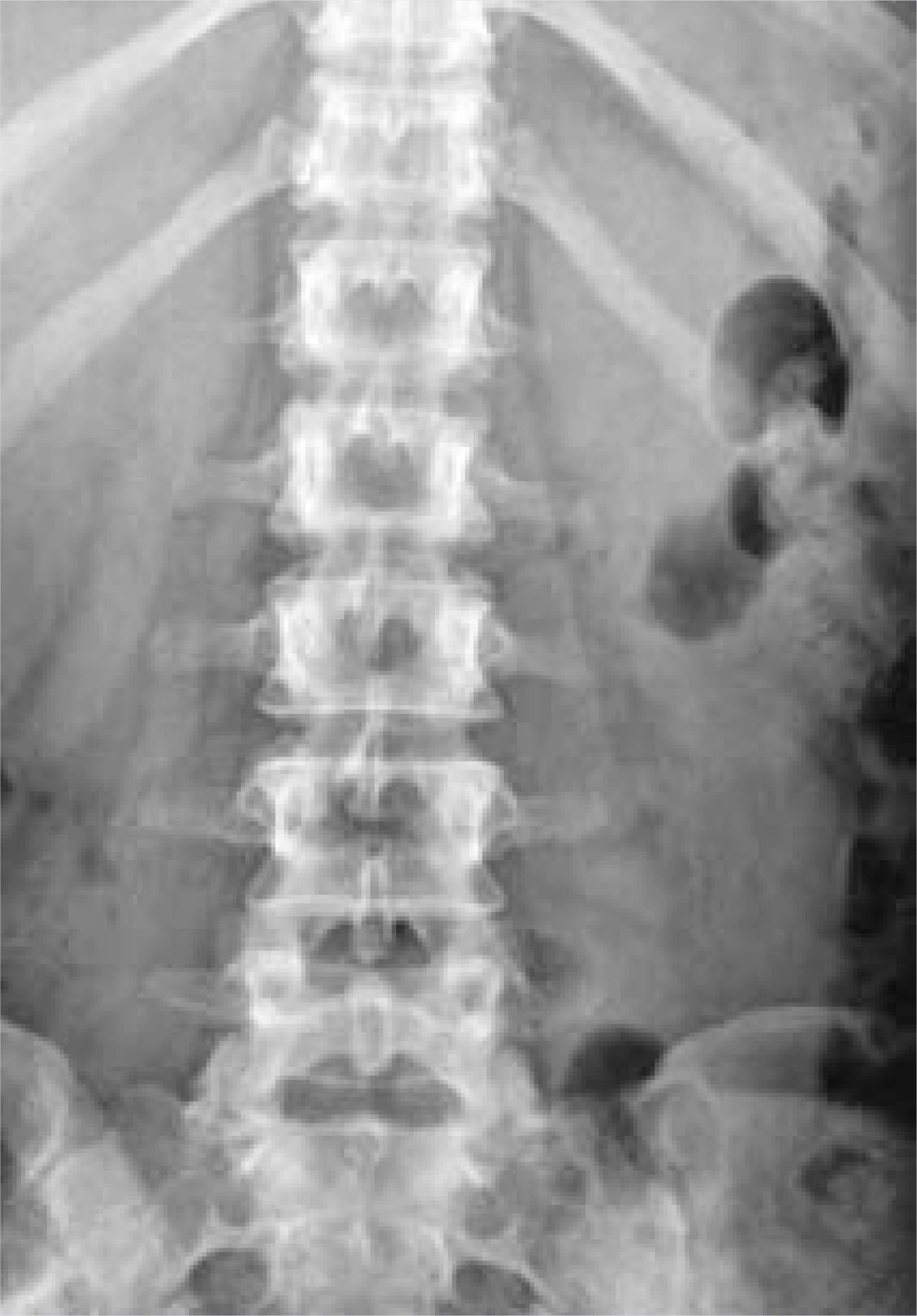
Amorphous silicon is also a photoconductor and can capture photons and generate electron-hole pairs. Unfortunately, silicon has a very low capability for absorption of high-energy photons, such as X-rays, and the detector would need to be 10- to 20-mm thick for most clinical radiography applications.3 Fabricating amorphous silicon devices of this thickness is not practical, and so such arrays would need to be made of crystalline silicon, which is currently very expensive. However, silicon can capture and convert visible light photons very well. When used with scintillators, such as cesium iodide, that absorb X-rays efficiently and emit visible light near the peak of the spectral sensitivity of silicon, photodiodes made of amorphous silicon can function as charge storage devices. This digital capture method uses a 2-step process called indirect conversion to transform X-ray photons first to visible light and then to an electric charge (Figure 2). The thin-film transistor and an external voltage can be used as a switch to permit the charge to flow from the silicon photodiode when a readout is desired (other combinations of charge storage devices and switches can be used). An example of a clinical image made with this approach can be seen in Figure 3.
Scintillators
Scintillators convert detected X-ray photons into visible light. A good scintillator is an efficient producer of light photons: 20 to 50 visible photons out per 1 keV of incoming X-ray energy are typical.3 Scintillators are usually made of a material with a high atomic number to achieve good X-ray absorption and an emitter substance that facilitates the conversion to visible photons. Some scintillators are crystalline, like cesium iodide. Scintillators such as gadolinium oxysulfide phosphors are granular, which can tend to scatter light and cause a loss of photons. Robin Windsor, CTO of Imaging Dynamics Company, explains “There are a lot of factors involved with designing a system so you do not get a ‘quantum sink’ effect, where you lose more light photons than the number of X-ray photons you started out with.” One way to limit the loss of visible light through scattering is to restrict or channel the photons. Cesium iodide can be evaporated to form discrete, parallel needles <20 microns in diameter that act as crystalline conduits.3 This structured design channels the photons and limits the spread of visible light, allowing a thicker scintillator layer to be used. The thicker the layer, the higher the X-ray absorption efficiency and the better the resolution. The visible light is next converted to an electric charge by various methods such as amorphous silicon photodiode circuitry, a charge-coupled device, or a complimentary metal- oxide semiconductor.
Charge-coupled devices
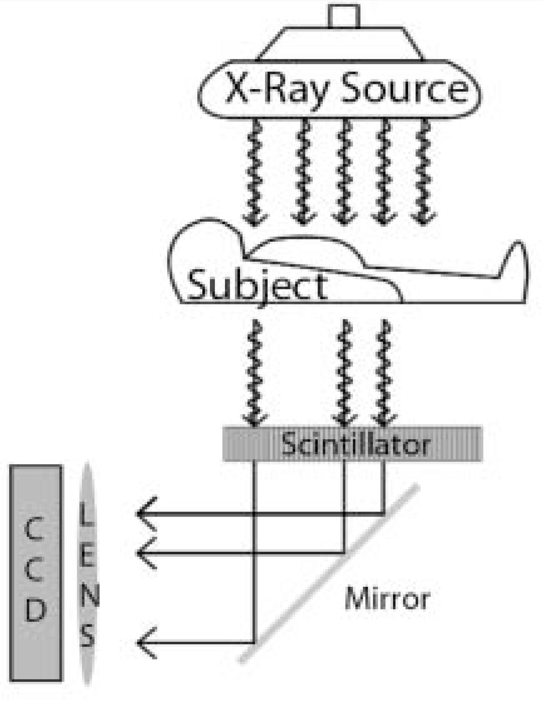
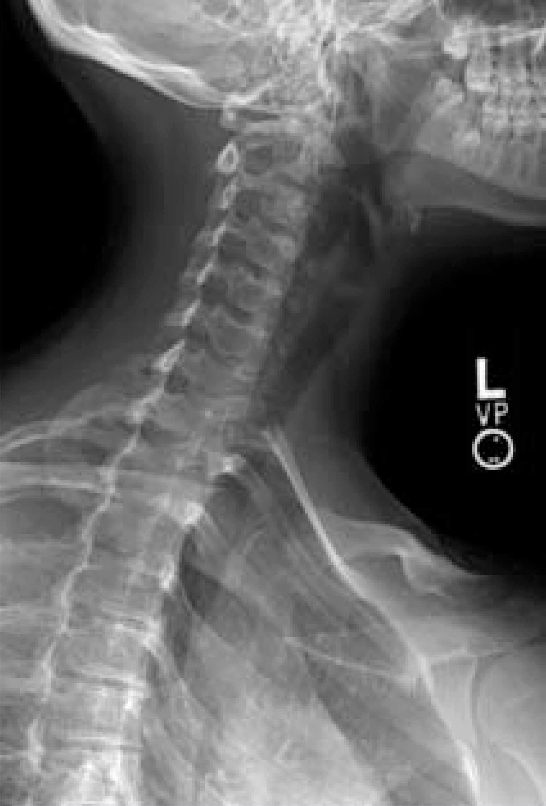
A charge-coupled device (CCD) is an integrated circuit composed of many light-sensitive cells (pixels) made of semiconductor material, typically silicon. The method by which the local charge is extracted from the original photon interaction site is reminiscent of the electron-hole pairs formed in the selenium photoconductor. Within the silicon crystal, electron storage sites or “potential wells” are formed by an electric field generated by voltages applied to electrodes on the surface of the CCD. By controlling the collapse and growth of adjacent wells, the charge can be “coupled” (output of one is input of the next) and moved from the original pixel to an integrated readout mechanism that assigns a digital value to the collected charge.4 When CCDs are used via indirect conversion methods in digital radiography, X-ray photons are converted into visible light photons by a scintillator and directed to the CCD by means of a lens or fiberoptic taper. A mirror may be used to deflect the scintillator output and remove the sensitive electronics in the CCD from the path of the X-ray beam (Figure 4). An example of a clinical image made with this approach can be seen in Figure 5. Modern CCDs have overcome initial technological problems of thermal noise by using semiconductor Peltier coolers. Early Peltier coolers were based on the heat differential that develops between two dissimilar metals that have a current run across them, wherein one side gets hot and the other side gets cold. Today’s solid state Peltier devices can cool CCD arrays, such as those in the Hubble space telescope, with no moving parts or coolant requirements (personal communication, Robin Windsor, March 2005).
Complimentary metal-oxide semiconductors
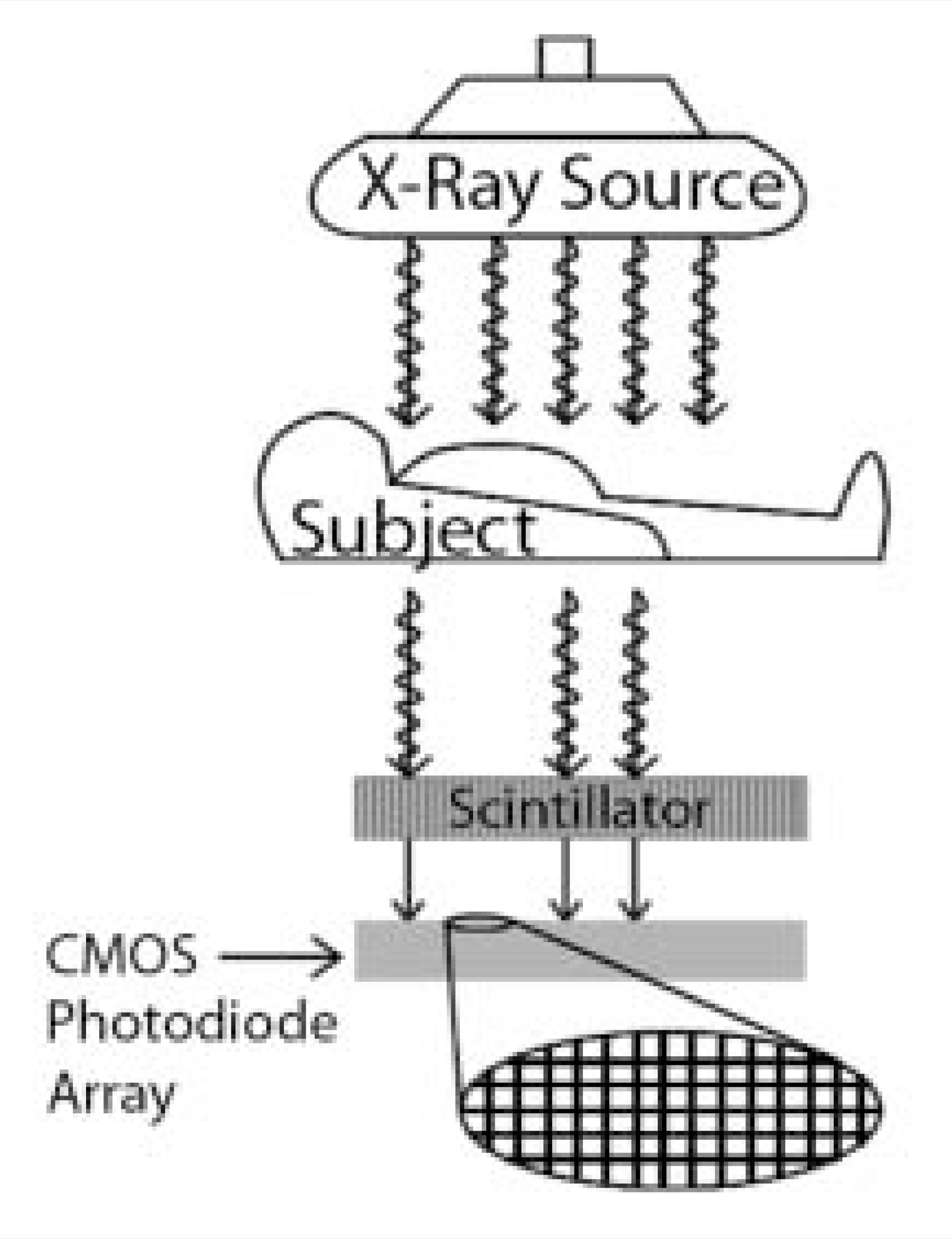
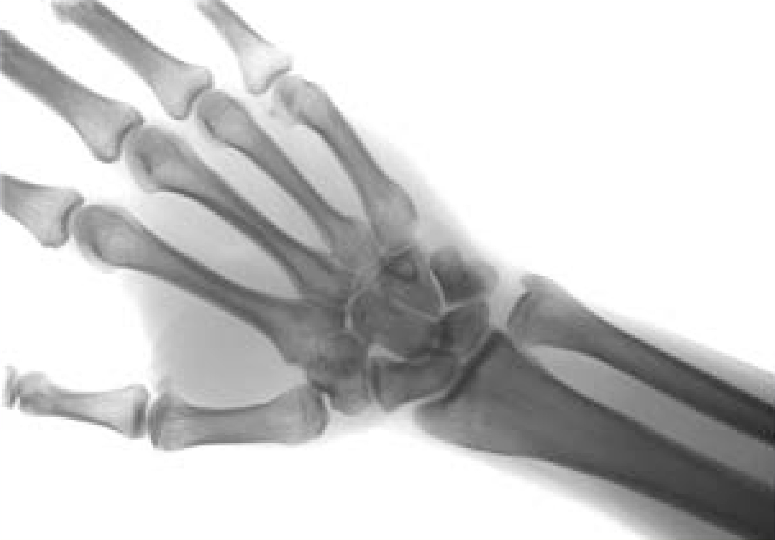
A complimentary metal-oxide semiconductor (CMOS) is a silicon circuit that can integrate analog photodiodes and digital timing and control circuitry on the same chip.5 The CMOS flat-panel sensor consists of a layer of a scintillator material, such as structured cesium iodide, that is directly deposited on a large-area formatted photodiode array. This can be overlaid with very narrow metal channels to read out the electric charges accumulated in the photodiodes6 (Figure 6). The CMOS technology brings the advantages of lower operating power requirements and a more standard lithography manufacturing process compared with CCD-based devices, resulting in lower fabrication costs. Many CMOS-based devices use a tiled array of chips, but newer technology has allowed construction of a large monolithic silicon wafer with a seamless 11-inch diagonal active area. The small pixel size of 50 μm and a 76% fill factor possible on a flat-panel imager in development6 can produce a spatial resolution of 10 lp/mm (Figure 7). In their study of CMOS applications for synchrotron radiation experiments, Yagi and colleagues7 write “A possibility that has not yet been explored is random readout. Since a CMOS photodiode array is read by column-row addressing, in principle it is possible to read only the pixels that are necessary for the purpose of the experiment. This will considerably reduce the readout time and increase the frame rate. Although this function has not been implemented, it will be a unique feature of CMOS imagers that is not achievable with the CCD.”
Clinical applications
For the radiologist, DR offers rapid image acquisition, a wide dynamic range, adjustable image processing after the image has been acquired (eg, contrast en-hancement through gray-scale manipulation and unsharp masking, zoom capability, and more), and immediate distribution of the image to remote locations. The clinical benefits of DR go beyond increased productivity and reduced radiation dose to include better image quality than traditional radiography, reflecting the higher detective quantum efficiency of this technology. Chotas and Ravin8 compared human observer performance by using postprocessed hard-copy images of a contrast-detail phantom from a digital chest radiography system and conventional screen-film radiograph. They reported that observers detected more smaller (<2.0 mm in diameter) test signals on the digital images. Even when X-ray exposure levels for the digital system were reduced by 20%, observers more readily detected signals with lower inherent subject contrast on digital images than on screen-film images. A more recent experimental study by Metz and colleagues9 using a chest phantom with an amorphous silicon flat-panel detector found that reducing the detector dose by 50% to 1.25 mGy (system speed, 800; 120 kVp) caused no significant loss in diagnostic performance in the lung fields, although overall lesion detection was significantly decreased.
Advanced clinical applications, such as dual-energy imaging for selective soft/hard-tissue discrimination, and tomosynthesis or 3-dimensional imaging for enhanced spatial visualization for both radiographic and mammographic applications, are being developed to take full advantage of DR technology.
Digital dual-energysubtraction imaging
Dual-energy subtraction imaging using DR has shown potential for the evaluation of coronary calcifications and lung disease. This technique may provide important clinical information early in the diagnostic process and spare some patients the higher cost and radiation burden of computed tomography (CT). In a recent study, patients with coronary calcifications confirmed by multidetector CT underwent digital radiography at 120 kVp and 60 kVp to generate 3 images, a standard postero-anterior chest view, a subtracted soft-tissue image, and a subtracted bone image. Evidence of cardiac calcification was seen in all cases confirmed by CT, and 3 patients had evidence of valvular and myocardial calcifications.10 Unfortunately, left and right calcifications were not equally visible in patients with CT-confirmed bilateral calcifications. Dual-energy subtraction imaging is also useful for diagnosis of lung disorders.11 The soft-tissue image can show focal opacities, such as nodules, that may be partly obscured in the standard view by overlying ribs or clavicles. The bone image can show calcification in benign pulmonary nodules as well as rib abnormalities that can mimic lung masses. DR manufacturers are developing differing approaches to provide this capability and may use either single exposure with special filters or rapid double exposure methods to achieve dual-energy subtraction images.
Digital tomosynthesis
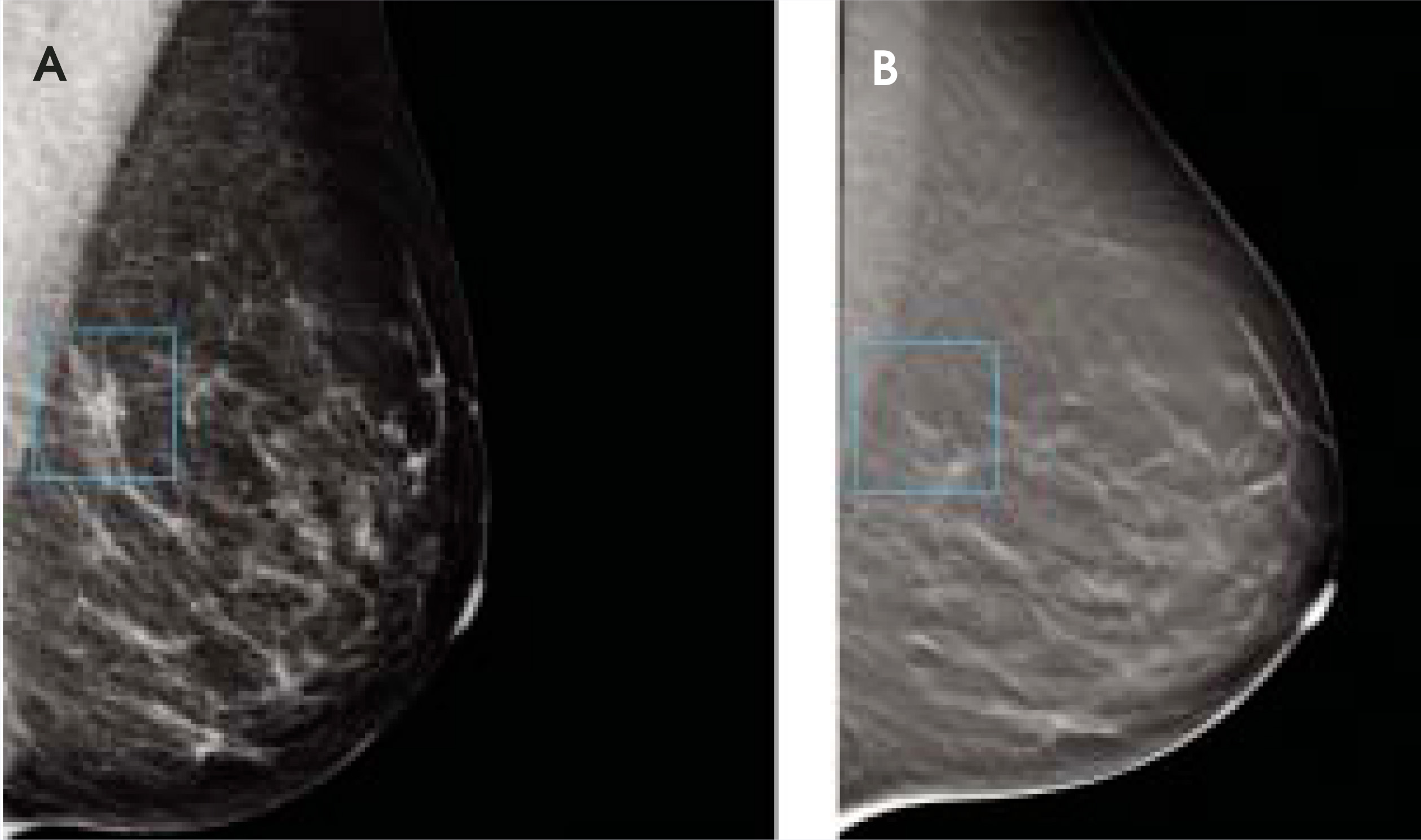
Digital tomosynthesis can bring 3-dimensional imaging to DR. In a laminography-like process, a sequence of images is acquired from an X-ray source moved to many different positions in a manner that keeps the target structures within a specific plane in focus while blurring overlying tissues. Digital radiography has significant advantages over traditional screen-film technology for tomosynthesis because the images can be processed retrospectively at the workstation to minimize the contribution of the out-of-plane, blurred portions and maximize the region of interest. This process is of great interest in mammography (Figure 8), for which up to 11 images are acquired in an arc around each breast during 7 seconds, with a total radiation dose less than that of a standard two-view mammogram. Results of initial pilot studies at Massachusetts General Hospital show that digital tomosynthesis can detect 16% more cancers compared with findings for conventional mammography and can reduce the false-positive rate by 85%.12 Stevens and colleagues13 used a head phantom of the upper cervical spine to evaluate the potential for digital circular tomosynthesis. They report that this technique effectively blurs the overlying jaw and skull structures and allows good visualization of the C1 and C2 vertebrae. They also studied this technique in mastectomy specimens and breast phantoms, and report improved visualization of breast tissue and acquisition of 3-dimensional information about calcification clusters. Digital tomosynthesis is also showing promise in evaluating arthritic changes in the hands,14 and for angiography, chest imaging, and dental imaging.15
Experience in thehealthcare industry
Although there is general agreement that digital capture radiography increases workflow and is cost efficient in the long term, it represents a considerable initial investment in equipment and time to transition a facility to this new technology. The decision is simpler for those considering construction of a new facility. When Dr. Ken Hager, managing partner of Advanced Imaging of Gadsden, (Gadsen, AL) decided to open his outpatient facility last November, he installed all digital technology: “Anyone opening a fairly current, up-to-date facility and not setting it up digital in the first place is asking for trouble because you will have to retool in pretty short order.” Dr. Hager chose a CCD-based system for his standard radiography needs because he felt the unit provided good images and was cost efficient. “This technology is basically off the shelf, and the most expensive part is $10,000 or so. Your cost of operation and risk of very expensive repairs are lower.” Dr. Hager cites lower radiation dose among the important advantages for DR technology, “We have a fair number of pediatric patients, and having as low a dose as possible is always desirable.” He also likes the direct linkage to picture archiving and communication systems (PACS) and radiology information systems (RIS). “DR is a lot faster for acquiring images, but also for cataloging. It saves us an enormous amount of archival-related costs because we’re not buying jackets, writing names on all those, and storing them.” In some instances, Dr. Hager likes to make copies of the images available to patients, who can take them home on an inexpensive compact disk to view on their home computer. Compared with plain films, fewer digital images are lost, and if a CD containing an image is lost, the original data are still available in the archive network. Dr. Hager is a strong proponent of computer-aided diagnosis (CAD), especially for his digital mammography units. With DR, it is easy to take advantage of CAD technology.
Dr. Robert Gould, Professor of Radiology and Medical Physicist at the University of California at San Francisco Medical Center, has experience with DR equipment from several manufacturers. He has been impressed with the consistently high image quality, “you have almost no repeats,” and the very fast examination time made possible with DR technology. “How you choose to use that shortened procedure time depends on the facility. A super busy facility might be able to cut down by a room... We went from 3 rooms to 2 rad rooms, and we probably could have handled the load with a single room, but then we wouldn’t have a backup.” Dr. Gould notes that because of the sophisticated technology and associated servo-mechanisms necessary for alignment and control, the maintenance and repair costs for DR will exceed those for screen-film equipment, but he believes that the dramatic improvement in workflow is well worth the extra expense of DR. “We are quite happy with the technology and will continue to invest in it.” For centers considering conversion to digital technology, the dilemma may be which system to use.
CR versus DR
Computed radiography (CR), like DR, offers significant advantages over traditional screen-film systems. Because the digital image can be corrected for under- or overexposure, CR can reduce the need for repeat examinations. Also, like DR, the digital output allows for chemical-free processing and fast data storage and retrieval. However, there are important differences between CR and DR.
Computed radiography devices use an imaging plate composed of photostimulable phosphors that store the X-ray photons within metastable energy traps. Like screen-film conventional systems, there is no integrated readout mechanism and the imaging plate must be processed separately to reveal the final digital image.16 The plate is scanned in the automated processor by a laser beam that releases the stored energy as visible light that is captured by a photomultiplier tube. A photomultiplier tube consists of a photo- emissive cathode and a series of dynodes in an evacuated glass enclosure. Electrons emitted after the photons strike the cathode are accelerated toward the series of dynodes, each at a progressively more positive potential. Electrons are added in a cascading effect at each dynode, ultimately generating as many as 105 to 107 electrons for each photon hitting the first cathode. This amplified signal is finally collected at the anode, where it can be measured and digitized.17 Computed radiography produces DICOM-compliant digital images that can be displayed on computer monitors and stored and distributed via PACS. The imaging plate is erased by exposure to visible light and can be reused. Most CR systems can be retrofitted to standard screen-film radiography systems, and imaging plates and cassettes are available in standard film sizes, facilitating an economical conversion to digital technology.
However, CR also has some relative disadvantages compared with DR, beginning with radiation dose. A recent experimental study by Uffmann and colleagues18 found that flat-panel DR required up to 45% less radiation exposure than did the phosphor-storage plate CR systems. According to Dr. Gould, “with CR, the quality of the image is dependent on the amount of radiation used. If you undershoot, you get a noisy image. If you overshoot, you still get an image, but you have given the patient more radiation.” In contrast, DR has a fixed setting, and Dr. Gould feels “the images are really excellent.” Another important difference is that DR examinations are much faster than those using CR. Results of a time-motion study at Mount Auburn Hospital, a community and teaching hospital affiliated with Harvard Medical School, found that DR was 4 times faster than CR for the total time to complete 2-view chest studies, with cassette reading and quality control accounting for 64% of the total examination time for CR.19 This means that DR equipment can handle more patients per square footage, which is a big advantage for centers considering costly renovation or expansion because of increased patient volume. This same increased productivity with DR means not only can existing staff handle greater numbers of patients, they can do so more effectively. Because the images are immediately available, technologists need not leave the examination room to process cassettes and can spend more of their time with each patient.
But the decision of which technology is best for a given institution may be more complex than previously thought. Preliminary results presented at the February 2005 Digital X-Ray and PACS Forum by Dr. Bruce Reiner,20 Maryland Institute of Medical Informatics at the University of Maryland School of Medicine (Baltimore, MD) show that al-though DR is faster than CR, the point at which DR becomes more cost efficient is at a mean patient arrival distribution of 13.5 patients per hour or 135 patients per room per day, which is an extremely high patient volume. Reiner is quoted as saying “in the current practice environment, CR is far more cost effective than DR. This is largely due to the relative imbalance between productivity gains (of DR) and reduced pricing (of CR).”
Computed radiography can be valuable for portable bedside or trauma applications where large DR systems would be too bulky. But here, too, DR is impinging on the CR market as newer portable DR systems are introduced.
Currently, the main advantages of CR are its lower cost, portability, and ability to integrate with existing X-ray systems. Many hospitals and imaging centers use both CR and DR systems. According to Dr. Gould, some DR systems cannot take cross-table lateral shots, and in studies requiring such views, a combination of CR and DR may be necessary. Ultimately, each center will have to evaluate its economic and productivity needs to find its way through this digital dilemma.
Conclusion
Digital radiography provides immediate clinical images of excellent quality that can be further enhanced after acquisition to broaden its diagnostic applications. Because of the inherent efficiencies of direct digital capture, the radiation dose can often be reduced. Integrated direct readout of the image data eliminates film processing and development, and storage and distribution of the digital images are efficient and convenient. There are currently several approaches used to deliver this capability, some of which are awaiting U.S. Food and Drug Administration approval. Important differences will no doubt be found among the methods used to provide digital capture of image data, and as this technology continues to evolve, knowledge of these differences will be important to radiologists looking to choose a digital imaging system for their applications.
References
- Chotas H, Dobbins J, Ravin C. Principles of digital radiography with large-area, electronically readable detectors: A review of the basics. Radiology. 1999;210:595-599.
- . 2005.
- X-ray conversion methods. 2005.
- The Encyclopedia of Astrobiology, Astronomy, and Spaceflight. 2005.
- Rocha J, Ramos N, Lanceros-Mendez S. CMOS X-rays detector array based on scintillating light guides. Sens Actuators. 2004;A110:119-123.
- Fujita K, Mori H, Kyuushima R. High resolution large formatted CMOS flat panel sensors for X-ray. 2003.
- Yagi N, Yamamoto M, Uesugi K, Inoue K. A large-area CMOS imager as an X-ray detector for synchrotron radiation experiments. J Synchrotron Radiat. 2004;11:347-352.
- Chotas H, Ravin C. Digital chest radiography with a solid-state flat-panel X-ray detector: Contrast-detail evaluation with processed images printed on film hard copy. Radiology. 2001;218:679-682.
- Metz S, Damoser P, Hollweck R. Chest radiography with a digital flat-panel detector: Experimental receiver operating characteristic analysis. Radiology. 2005;234:776-784.
- Gilkeson R, Novak R, Sachs P. Digital radiography with dual-energy subtraction: Improved evaluation of cardiac calcification. Am J Radiol. 2004;183:1233-1238.
- MacMahon H. Imaging Tech News.
- Rafferty E. Dec Imaging Econ.
- Stevens G, Birdwell R, Beaulieu C. Circular tomosynthesis: Potential in imaging of breast and upper cervical spine–Preliminary phantom and in vitro study. Radiology. 2003;228:569-575.
- Duryea J, Dobbins J, Lynch J. Digital tomosynthesis of hand joints for arthritis assessment. Med Phys. 2003;30:325-333.
- Dobbins J, Godfrey D. Digital X-ray tomosynthesis: Current state of the art and clinical potential. Phys Med Biol. 2003;48:R65-R106.
- Ravin C.
- Photomultiplier tube. 2005.
- Uffmann M, Schaefer-Prokop C, Neitzel U. Skeletal applications for flat-panel versus storage-phosphor radiography: Effect of exposure on detection of low-contrast details. Radiology. 2004;231:506-514.
- DeMaster D. Digital radiography offers major productivity gains over computed radiography: Results of a time-motion study. Appl Radiol. 2001;30(3):28-31.
- Batchelor J. New research shows CR more cost-effective than DR. 2005.
- Wiley G. Dec Imaging Econ. 2004. 2005.
Citation
. Digital diversity dilemma. Applied Radiology. 2005;34(5):34-45. doi:10.37549/AR1336.