Fluoroscopically Guided Bone Marrow Biopsy
Applied Radiology — Vol. 49 , Issue 4 , pp. 20 -25
DOI: 10.37549/AR2664
Published: July 1, 2020
1 Medical College of Wisconsin, Milwaukee, WI
Categories
Bone marrow sampling and analyses are performed to obtain marrow specimens in a minimally invasive, reproducible, time efficient manner to diagnose hematologic disorders such as lymphoma, multiple myeloma, and leukemia.1,2,3,4,5,6,7,8 The American Cancer Society estimates 178,520 cases of these diseases will be diagnosed in the United States in 2020.9
Bone marrow biopsies, which are also used to evaluate disease progression and treatment response, historically have been performed under palpation guidance. While palpation-guided marrow sampling is successful, complications can arise, especially in larger patients.1,2,3 CT-guided bone marrow biopsy, has also been described in the literature;1 the technique is straightforward and relatively low risk.10,11
Fluoroscopy offers a second image guided approach, although an effective discussion of fluoroscopically guided marrow sampling is difficult to find in the literature.10,11 This manuscript describes such an approach that replicates the needle path of CT-guided biopsy.
Imaging Anatomy
A thorough knowledge of the osseous pelvis is imperative for successfully, reproducibly, and safely completing fluoroscopically guided marrow biopsy, which poses unique challenges due to the superimposition of various structures in this area.
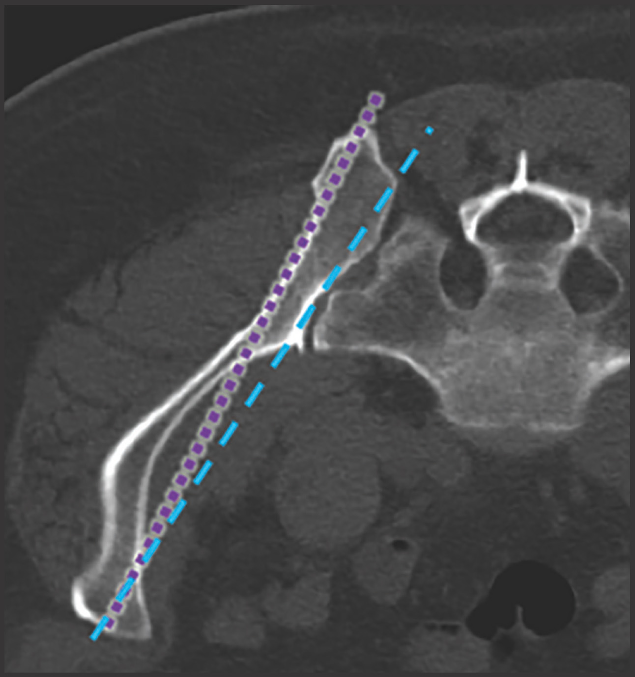
The posterior ilium, which is one of the widest parts of the ilium, contains abundant marrow, is easily accessible, and is often targeted for sampling (Figure 1A).5,10,11,12,13 During CT-guided biopsies (Figure 1B), the needle traverses only skin, subcutaneous fat, and the posterior iliac cortex prior to accessing the bone marrow.1 Directing the needle along the long axis of the posterior ilium in the anteroposterior (AP) dimension allows for a larger sample size and limits injury to other pelvic structures.1,12,14
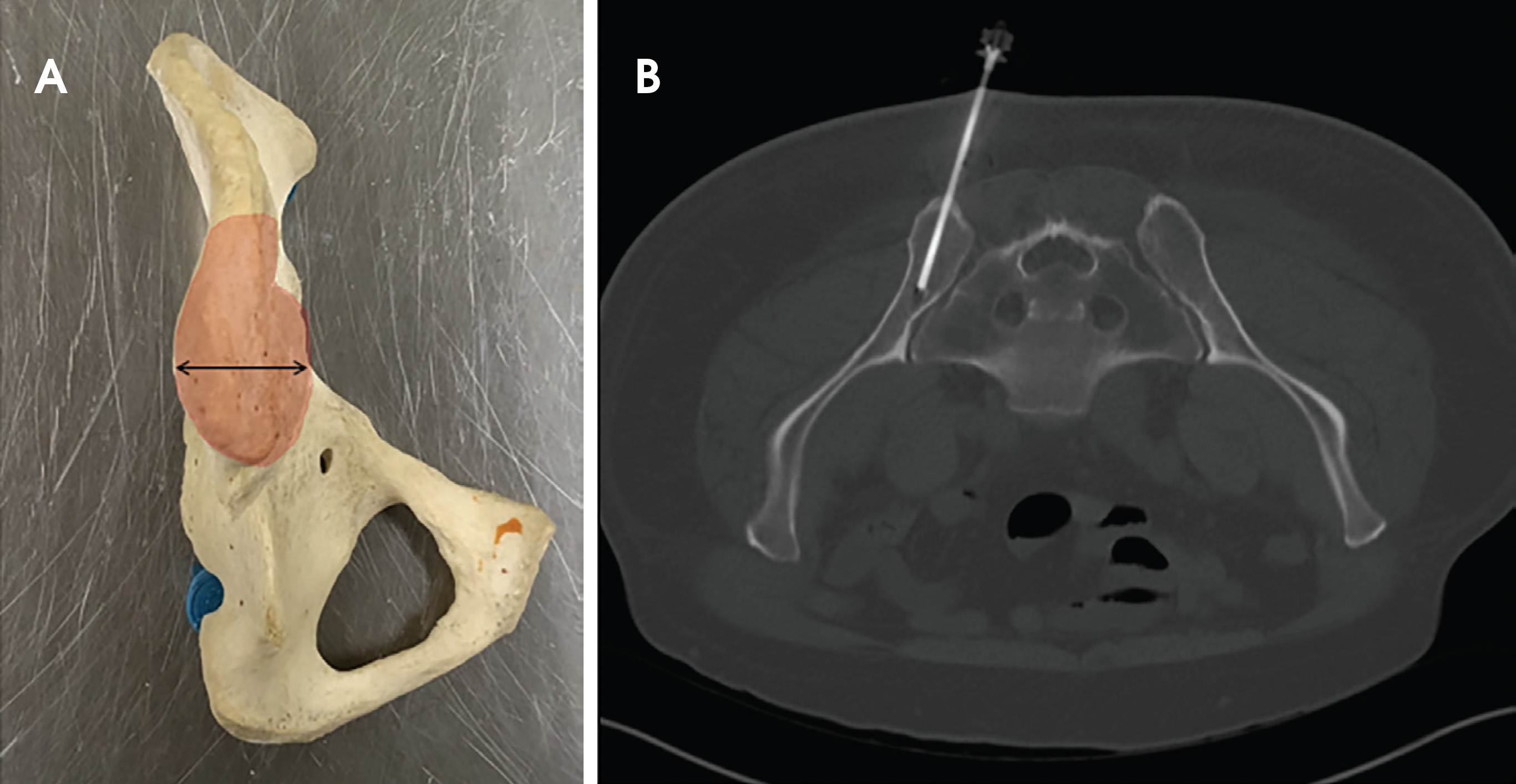
The CT-guided biopsy approach through the posterior ilium can be replicated with fluoroscopy. As can be seen in Figure 1B, the posterior aspect of the ilium is wider than the anterior aspect. Properly identifying the medial and lateral cortex of the narrowest part of the ilium and keeping the needle centered between the two limits complications and ensures an intraosseous needle position.
An AP fluoroscopic image is obtained with the patient lying prone (Figure 2B); the sacroiliac joint is clearly visible. The anatomic configuration of the sacroiliac joint results in a complex appearance on fluoroscopy. The most relevant portion of the joint is its ventral/superior segment, which appears the largest on the AP image. This segment comprises the interface between the S1 ala and the adjacent ilium and represents the lateral-most portion of the sacroiliac joint on the AP image
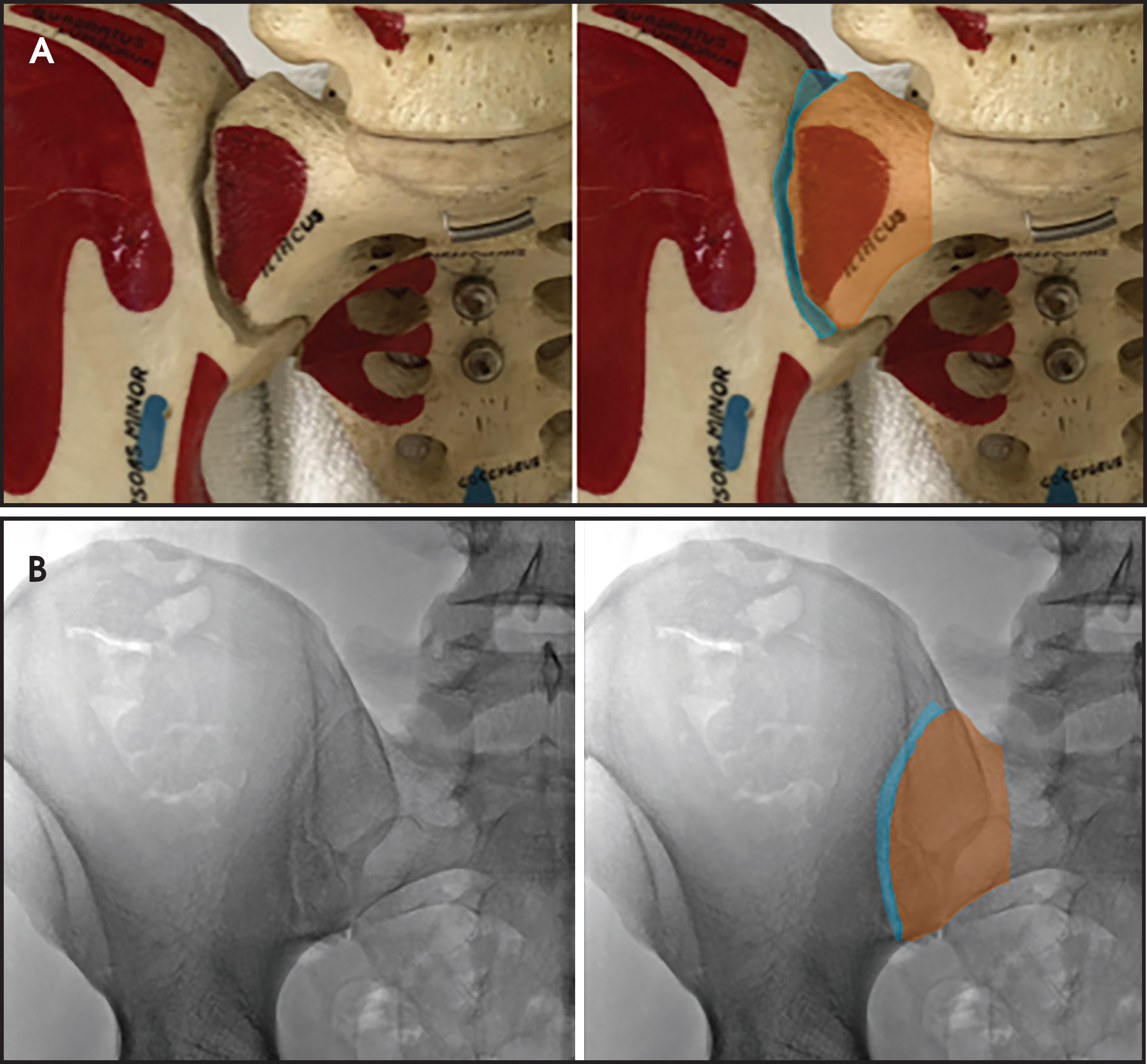
The lateral boundary of the ventral/superior aspect of the sacroiliac joint is formed by the ilium and is an important landmark (Figure 3B). The AP view of the posterior pelvis reveals a vertical sclerotic line (Figure 3B) that intersects with the lateral margin of the ventral/superior portion of the sacroiliac joint. The sclerotic line is a critical anatomic landmark to identify, as it represents the summation of the lateral border of the posterior ilium in the AP dimension. After some manipulation of the fluoroscopic beam angle, these two landmarks will direct the intended course of the needle.
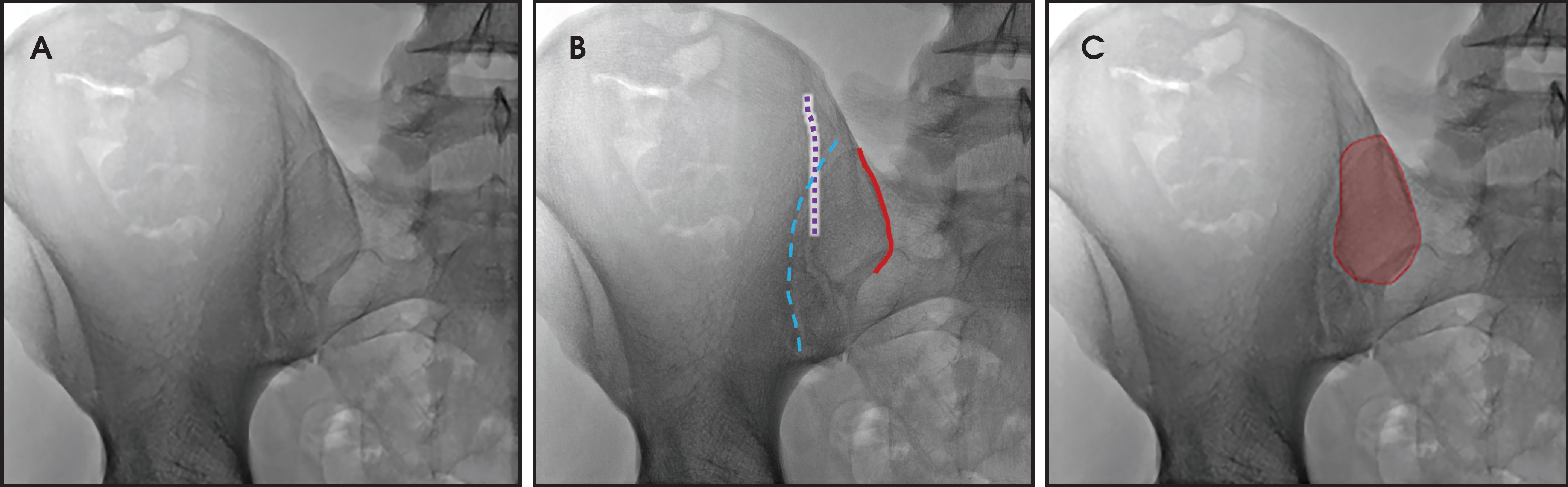
The long axis of the posterior ilium is obliquely oriented, as can be seen in Figure 1B. Therefore, the fluoroscopic beam must also be oriented obliquely in order to be parallel to the long axis of the posterior ilium (Figure 3C). This orientation optimizes the width of the desired biopsy target.
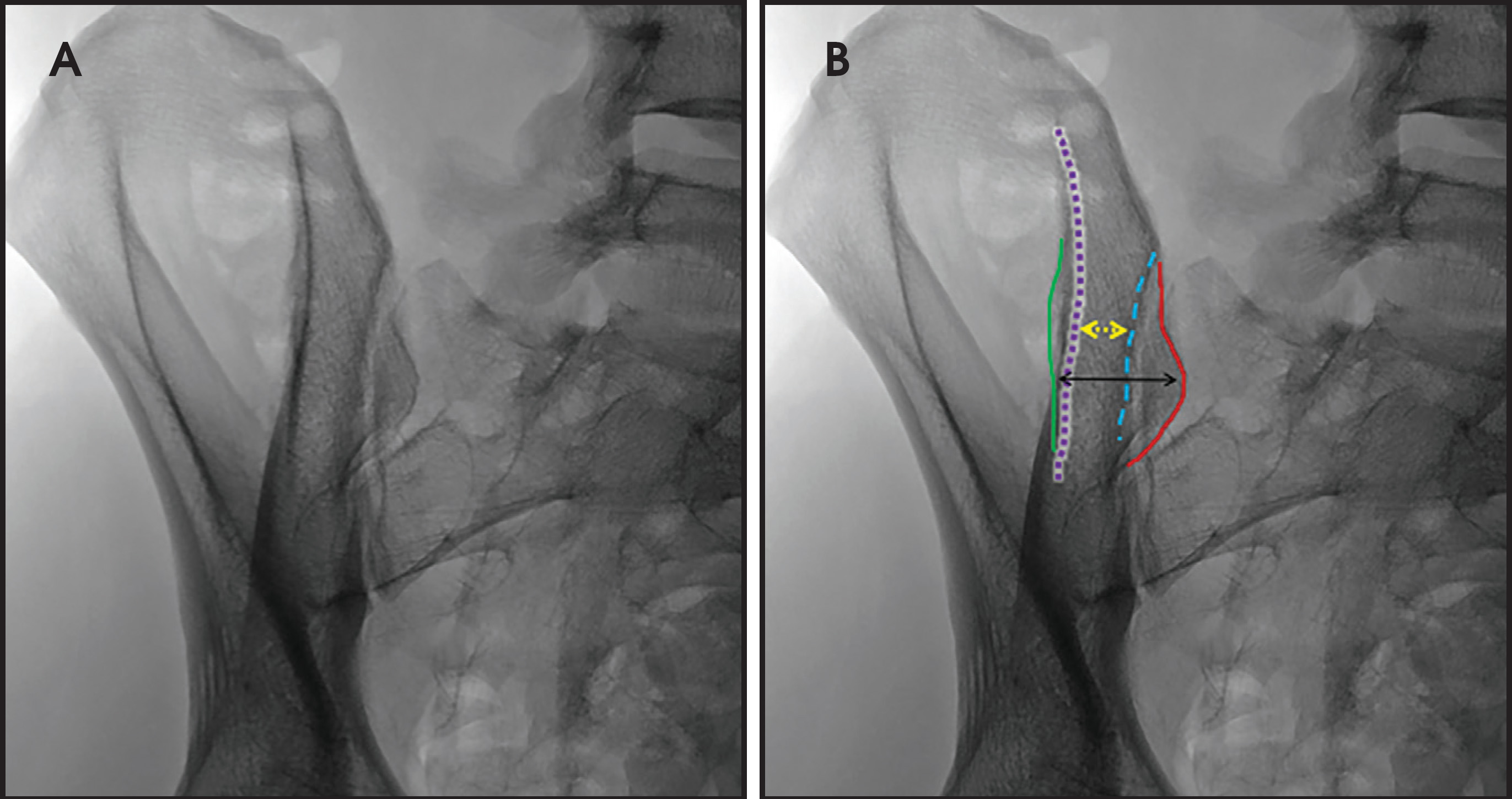
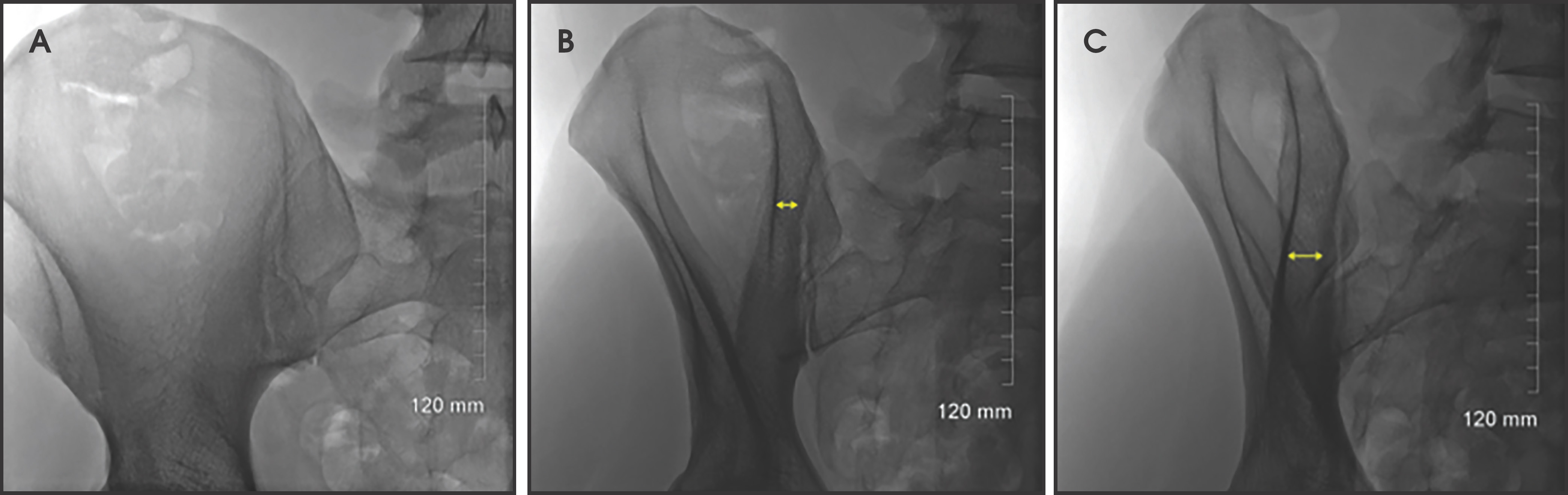
The key anatomy for the procedure is the space located between the lateral, vertical sclerotic line (Figure 4B, dotted purple line) and the medial border of the ilium/lateral border of the sacroiliac joint (Figure 4B, dotted blue line). This space represents the anterior aspect of the ilium, which is narrower than the posterior ilium (Figure 1). Keeping the biopsy needle between these lines ensures an intraosseous course (Figure 4). Therefore, the obliquity of the fluoroscopic beam providing the widest space between these lines allows for the greatest margin of safety and increases the likelihood of acquiring a longer biopsy sample. Ideal obliquities are typically between 20-30 degrees.
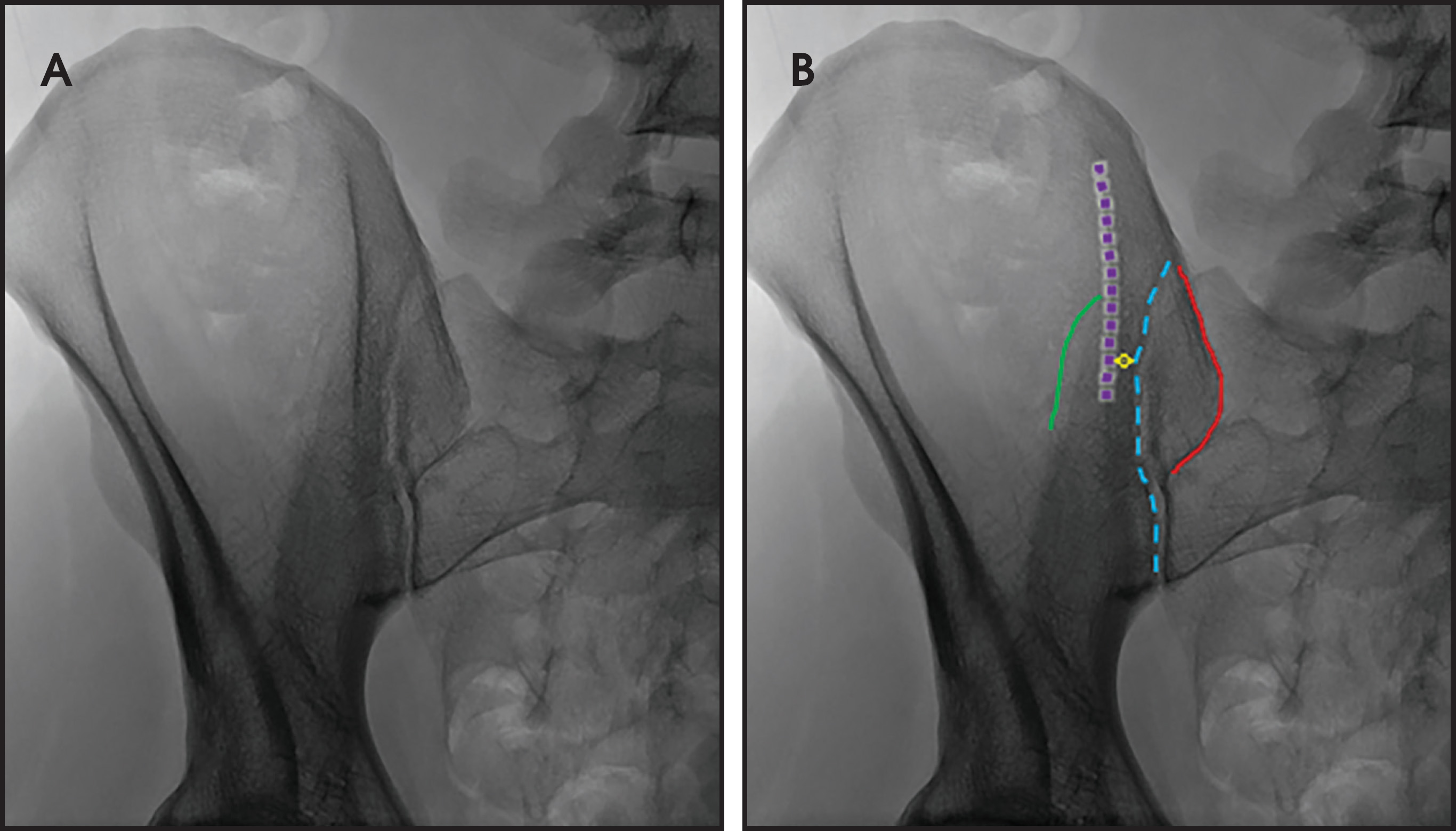
Increasing the image obliquity from 14.8 degrees to 25 degrees provides the largest transverse dimension between the lateral and medial iliac margins along the biopsy tract in this patient.
Of note, the thickness, conspicuity, and craniocaudal extent of the medial border varies with the individual and chosen obliquity. The medial cortex has a more undulating contour, as well as greater variability in thickness and density than that of the lateral side. Additionally, the medial and lateral cortices are not parallel; they converge anteriorly and diverge posteriorly (Figure 6). Therefore, each line will be optimally viewed with different obliquities; typically, the medial border is more clearly seen with higher obliquities given its orientation in relation to the lateral border. Note how the lateral border (dotted purple line) is sharper and better delineated while the medial border (dashed blue line) is more amorphous and less dense.
The potential landing zone margins can be identified fluoroscopically (Figure 5), although this is unnecessary. Identifying the narrower portion of the ilium anteriorly, as demarcated in Figure 5B and maintaining needle position within this region results in proper needle centering at the landing zone and ensures an intraosseous course.
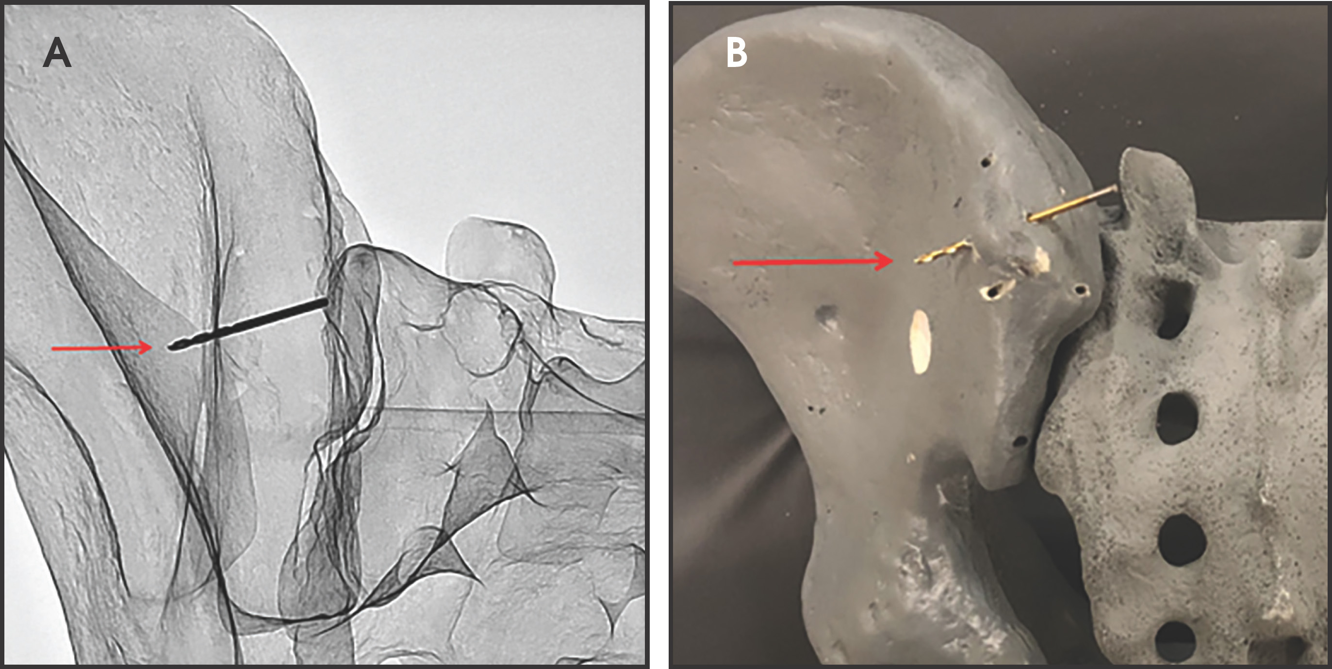
A model pelvis is used to demonstrate the importance of the medial and lateral landmarks. Figure 7 demonstrates a drill bit positioned such that it breaches the lateral sclerotic line (red arrow); the accompanying photograph demonstrates the drill bit through the lateral cortex (red arrow).
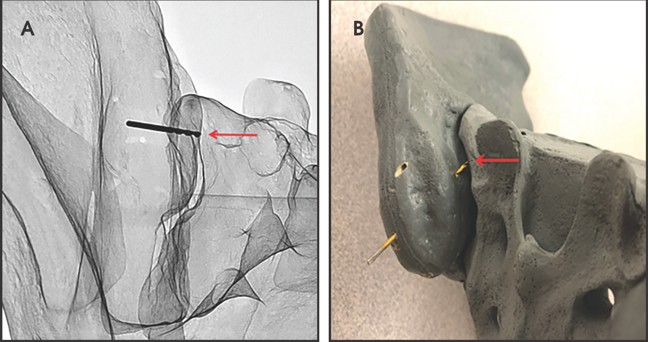
A similar approach was used for the medial sclerotic line with the drill bit extending through the medial cortex into the ligamentous portion of the sacroiliac joint (Figure 8).
Technique
Reviewing pelvic cross-sectional studies prior to the procedure, if available, can help guide the level of entry and initial tube angulation. The patient is positioned prone on the fluoroscopy table and the fluoroscopic beam is oriented to maximize distance between the medial and lateral borders of the ilium, typically centered at the mid S1 level (Figure 9).
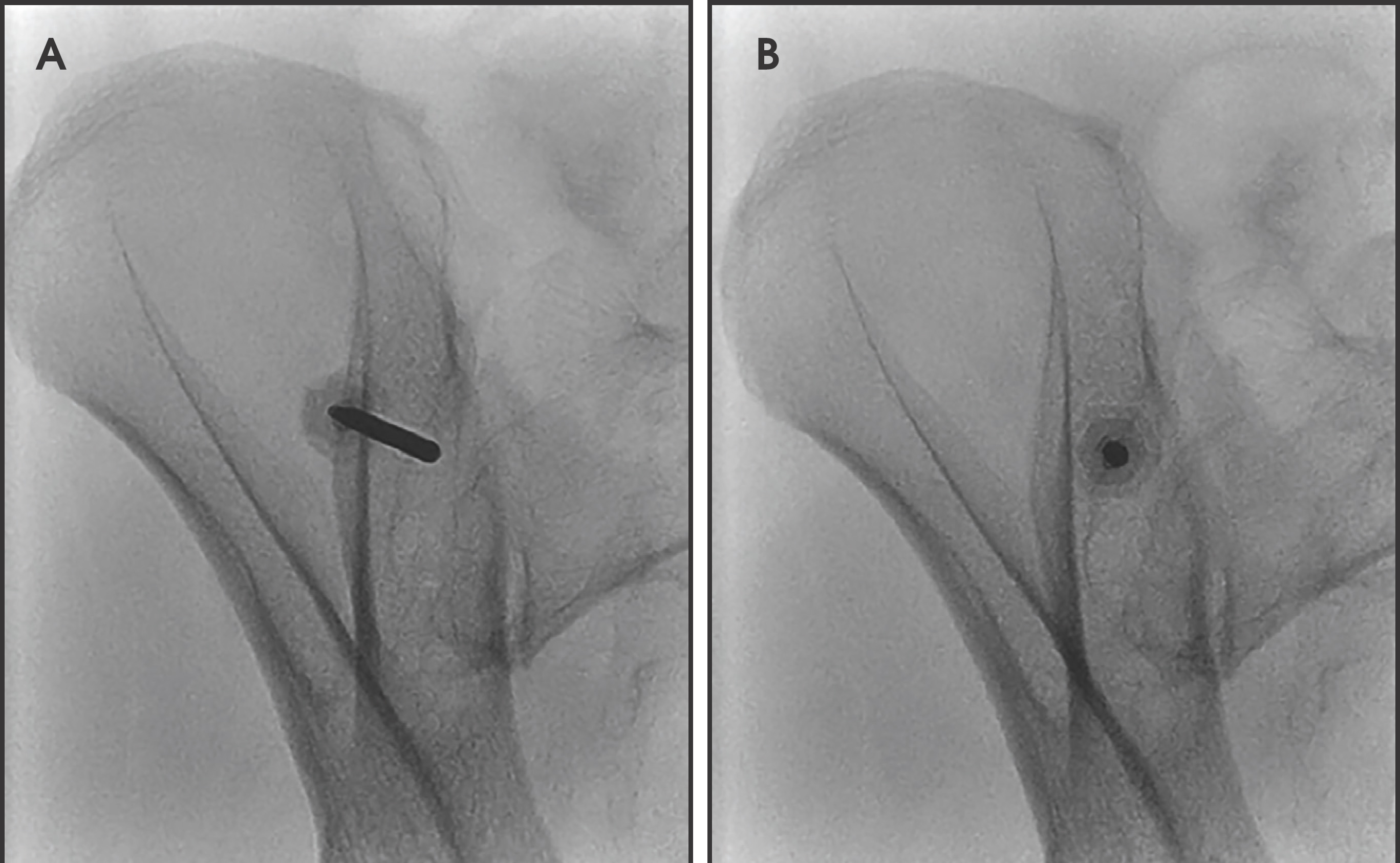
A hemostat is placed at this site, the skin is marked with a sterile marker, and the site is prepped. The skin, deeper soft tissues, and the periosteum are anesthetized with 1% lidocaine. A small skin incision is made and the biopsy device is introduced.4,7,16 Under fluoroscopic guidance, a hemostat (to limit radiation exposure to the operator’s hand) is used to orient the needle parallel to the fluoroscopic beam (Figure 10). The needle is then advanced through the subcutaneous tissues to the posterior ilium using intermittent fluoroscopy to ensure needle orientation is maintained.
The biopsy device is then advanced 0.5-1.0 cm into the posterior ilium; cranial or caudal angulation can be performed during aspiration to limit potential core sample artifacts (see Discussion). At this location, a 1-2 mL, non-heparinized aspirate is obtained via syringe and given to the cytotechnologist. Once the cytotechnologist identifies spicules in the initial aspirate, a 10 mL syringe containing 1 mL of heparin is attached to the device, and a total volume of 8-10 mL of aspirate is obtained. If more tests are required, additional heparinized and/or non-heparinized aspirate may be necessary.
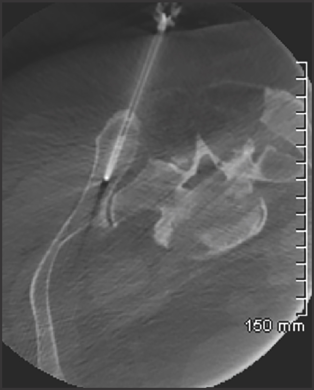
After the necessary aspirate volume is obtained, alignment of the needle is confirmed with fluoroscopy. A biopsy is obtained by advancing the device into the ilium until it is hubbed at the skin, resistance is met (possibly contacting a cortical margin), or up to 5 cm in anteroposterior depth is reached (whichever comes first) (Figure 11). The device is then withdrawn. The core sample is carefully extracted from the needle and collected by the cytotechnologist.
Many patients tolerate the procedure with local anesthetic only.15 However, others require conscious sedation for anxiety and/or pain control. If the procedure is performed with conscious sedation, the patient is monitored per institution protocol. After the procedure, the patient is discharged with standard post-procedural instructions.
Discussion
The details of the histopathologic evaluation of the aspirate and core samples including the pathologic diagnosis are beyond the scope of this article, but a cursory explanation is warranted.
The literature recommends using either a 10 mL or 20 mL syringe to obtain the bone marrow aspirate to create negative pressure during aspiration. The first 1-2 mL of aspirate is obtained without anticoagulant to preserve cell morphology.6 An in-room cytotechnologist is ideal to evaluate the sample for spicules, which represent fragments of relatively intact marrow containing the stromal and hematopoietic components and indicating an informative sample. The initial aspirate is most likely to represent true marrow. As the elapsed time from needle penetration into the cancellous cavity increases, there is a greater probability of hemodilution with peripheral blood.5,6,8 Additional syringes with or without an anticoagulation agent are often obtained for additional diagnostic tests, including flow cytometry, immunophenotypic analysis, cytogenetics, and molecular genetic techniques. If an adequate aspirate is not obtained, the cytotechnologist may request another marrow specimen in order to create a touch imprint for cytological examination.2,6
The most common reason no spicules may be identified under imaging guidance is underlying pathology such as hairy cell leukemia, idiopathic myelofibrosis, aplastic anemia, leukemias associated with fibrosis, and even hypercellular conditions. Extended aspiration time at the index site is discouraged due to the increasing chance of hemodilution with peripheral blood.2,5,6,17 An attempt can be made to angle the needle a few degrees cranially or caudally in order to direct it 1.5 - 2.0 cm away from the original site and re-enter the posterior ilium, allowing for a different aspiration site/biopsy tract.4 After discussion with hematopathology, often no more than two attempts at obtaining spicules are made.
The bone marrow aspirate and core biopsy are complementary. The literature recommends obtaining a marrow specimen of at least 1.5 cm.2,6 Since the biopsy represents only a small sample of the entire available bone marrow, larger diameter and longer cores are preferable, although diagnoses can be made on smaller samples.
The literature recommends performing a biopsy 1.5 - 2.0 cm away from the aspirate site to avoid depleting components of the biopsy specimen, aspiration artifacts, and damaged specimens.2 Bone marrow aspiration and biopsy may be performed at the same site; however, this increases the chance of obtaining an inadequate sample, especially with a relatively small biopsy specimen.5 In our experience, biopsy quality has not been significantly compromised by acquiring the biopsy at the same site as the aspirate. Using the technique described in this article, typically results in a longer sample increasing the distance from the aspiration site (for at least a portion of the specimen), even if the needle is not redirected between the aspiration and biopsy. If a separate site is needed or desired, retracting the biopsy needle to the posterior iliac cortex and redirecting it either cranially or caudally will allow for utilization of two separate sites.
Conclusion
This fluoroscopic technique for bone marrow sampling emulates the preferred needle course seen with CT and removes major nerves, vessels, and organs from the trajectory of the biopsy device, eliminating the potential for arteriovenous fistulas, gluteal compartment syndrome, pseudoaneurysms, retroperitoneal hemorrhage, compromised sacral canal/foramina, sciatic nerve injury, and death, all of which have been described in the literature.1,2,3,12,18 In addition, knowledge of the bony landmarks seen on fluoroscopy limits the potential for injury to the sacroiliac joint that can cause early arthritic change and subsequent chronic pain.
References
- Badiola C, Scappaticci F, Brahaj D. CT Guided Bone Marrow Aspiration and Core Biopsy. Open Journal of Radiology;2((2)). doi:10.4236/ojrad.2012.
- Bain B. Bone Marrow Trephine Biopsy. Journal of Clinical Pathology. 2001;54((10)):737-742. doi:10.1136/jcp.54.10.737.
- Bain B. Bone Marrow Biopsy Morbidity and Mortality. British Journal of Haematology. 2003;121((6)). doi:10.1046/j.1365-2141.2003.04329.x.
- Berenson J, Yellin O, Blumenstein B. Using a Powered Bone Marrow Biopsy System Results in Shorter Procedures, Causes Less Residual Pain to Adult Patients, and Yields Larger Specimens. Diagnostic Pathology. 2011;6((1)). doi:10.1186/1746-1596-6-23.
- Islam A. Bone Marrow Aspiration before Bone Marrow Core Biopsy Using the Same Bone Marrow Biopsy Needle: A Good or Bad Practice?. Journal of Clinical Pathology. 2006;60((2)). doi:10.1136/jcp.2006.037341.
- Lee S, Erber W, Porwit A. ICSH Guidelines for the Standardization of Bone Marrow Specimens and Reports. International Journal of Laboratory Hematology. 2008;30((5)). doi:10.1111/j.1751-553x.2008.01100.x.
- Reed L, Raghupathy R, Strakhan M. The OnControl Bone Marrow Biopsy Technique Is Superior to the Standard Manual Technique for Hematologists-in-Training: a Prospective, Randomized Comparison. Hematology Reports. 2011;3:60-64. doi:10.4081/hr.2011.e21.
- Riley R, Williams D, Ross M. Bone Marrow Aspirate and Biopsy: A Pathologist’s Perspective. II. Interpretation of the Bone Marrow Aspirate and Biopsy. Journal of Clinical Laboratory Analysis. 2009;23((5)). doi:10.1002/jcla.20305.
- Cancer Facts & Figures. 2020.
- Friedlis M, Centeno C. Performing a Better Bone Marrow Aspiration. Physical Medicine and Rehabilitation Clinics of North America. 2016;27((4)). doi:10.1016/j.pmr.2016.06.009.
- Hernigou J, Alves A, Homma Y. Anatomy of the Ilium for Bone Marrow Aspiration: Map of Sectors and Implication for Safe Trocar Placement. International Orthopaedics. 2014;38((12)). doi:10.1007/s00264-014-2353-7.
- Konda B, Pathak S, Edwin I. Safe and Successful Bone Marrow Biopsy: An Anatomical and CT-Based Cadaver Study. American Journal of Hematology. 2014;89((10)). doi:10.1002/ajh.23790.
- Hwang K, Kim J, Lee S. A Thickness Map of Iliac Bone of Korean Adults. Journal of Craniofacial Surgery. 1997;8((4)). doi:10.1097/00001665-199707000-00009.
- Lawson T, Foley W, Carrera G. The sacroiliac joints: anatomic plain roentgenographic, and computed tomographic analysis. Journal of Computer Assisted Tomography. 1982;6((2)). doi:10.1097/00004728-198204000-00015.
- Johnson H, Burke D, Plews C. Improving the Patient’s Experience of a Bone Marrow Biopsy – an RCT. Journal of Clinical Nursing. 2008;17((6)):717-725.
- Voigt J, Mosier M. A Powered Bone Marrow Biopsy System versus Manual Methods: a Systematic Review and Meta-Analysis of Randomised Trials. Journal of Clinical Pathology. 2013;66((9)):792-796. doi:10.1136/jclinpath-2013-201605.
- Puhakka K, Melsen F, Jurik A. MR Imaging of the Normal Sacroiliac Joint with Correlation to Histology. Skeletal Radiology. 2004;33((1)). doi:10.1007/s00256-003-0691-4.
- Wang D, DuBois M, Tutton S. Complications in Musculoskeletal Intervention: Important Considerations. Seminars in Interventional Radiology. 2015;32((2)). doi:10.1055/s-0035-1549447.
Citation
. Fluoroscopically Guided Bone Marrow Biopsy. Applied Radiology. 2020;49(4):20-25. doi:10.37549/AR2664.