Imaging of upper cervical spine injuries – Part III: C2 below the dens
Applied Radiology — Vol. 33 , Issue 7 , pp. 9 -21
DOI: 10.37549/AR1266
Published: July 1, 2004
Categories
[Editor’s note: The first article in this series was: West OC. Imaging of upper cervical spine injuries—Part I: C0–C1. Appl Radiol. 2002; 31(2):23-32. The second article in this series was: West OC, Bilow RM, Jarolimek AM. Imaging of upper cervical spine injuries—Part II: The dens. Appl Radiol. 2003;32(2):30-38.]
This is the third in a series of articles that review the radiography and computed tomography of upper cervical spine injuries. The intent of this series of pictorial essays is to illustrate the array of spinal injuries in wide breadth, with a heavy emphasis on images under the motto, “few words, many pictures.” Part I of this series covered fractures of C0–C1, and Part II of this series covered fractures of the dens.1,2 This article concludes this series by focusing on fractures of the C2 neural arch, body, and lateral mass. It will attempt to clarify the anatomy of the axis vertebra, address the Effendi classification scheme, differentiate the classical “hangman’s fracture” from true traumatic spondylolisthesis (TS), and discuss classification schemes for both TS and other C2 body fractures. The article will end with examples of C2 lateral mass fractures and other C2 fractures not previously addressed.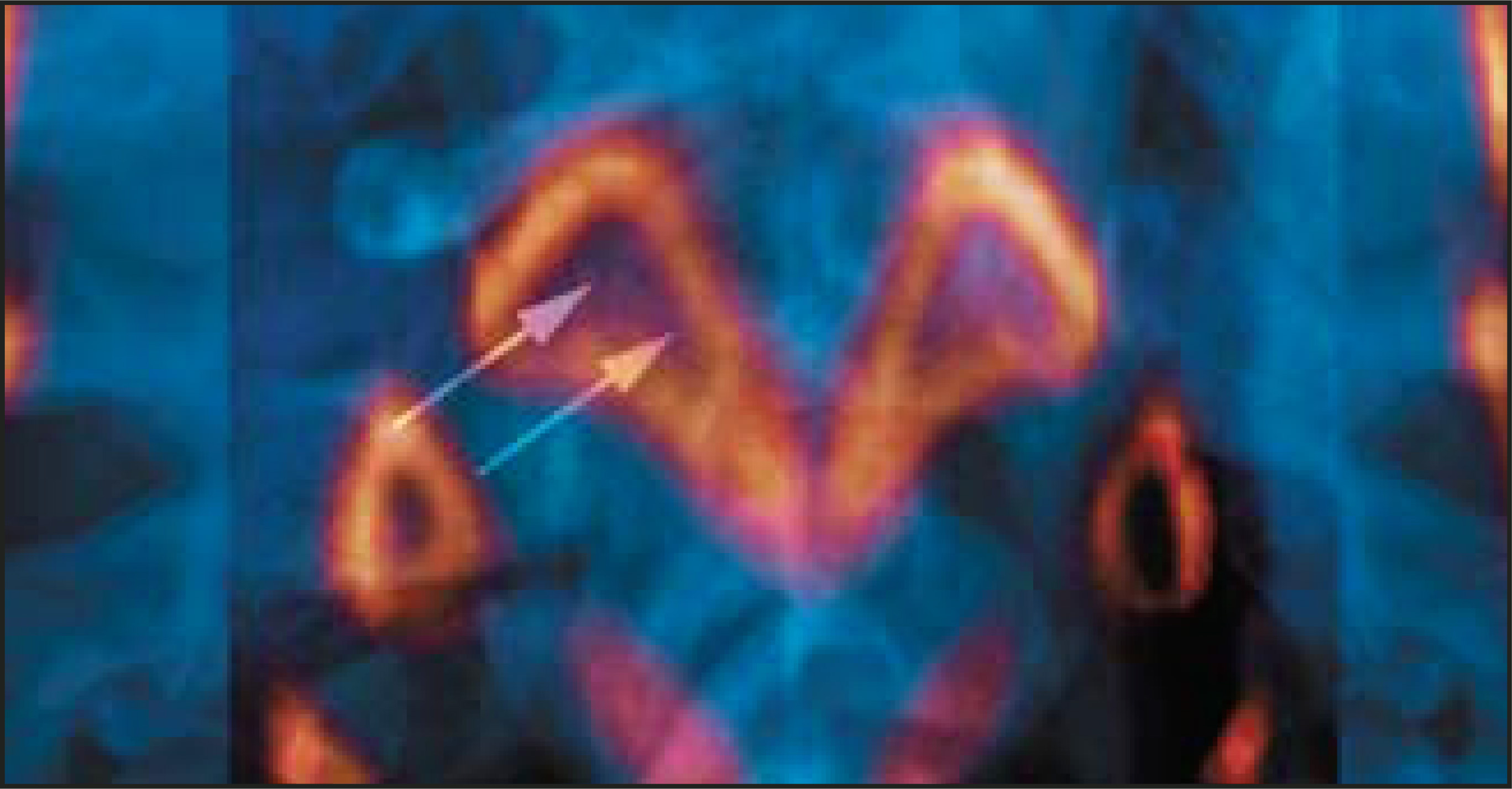
Anatomy
In order to accurately describe C2 injuries, the anatomy of C2 must first be accurately defined. Over the years, there has been much discussion and discord regarding the location of the pedicle versus the pars interarticularis. The question is relevant because the terms have been used interchangeably in describing hangman’s fractures. After a thorough literature search, we were unable to find any embryological text describing the origins of these two segments. Therefore, we have chosen to rely on observational anatomic surveys. We concur with Ebraheim and colleagues3 who define the pedicle of C2 as the slip of bone posterolateral to the vertebral body and anteromedial to the transverse foramen, while the pars interarticularis is the slip of bone between the superior and inferior articular surfaces (Figure 1). We use the pleural form, partes interarticulares, where appropriate.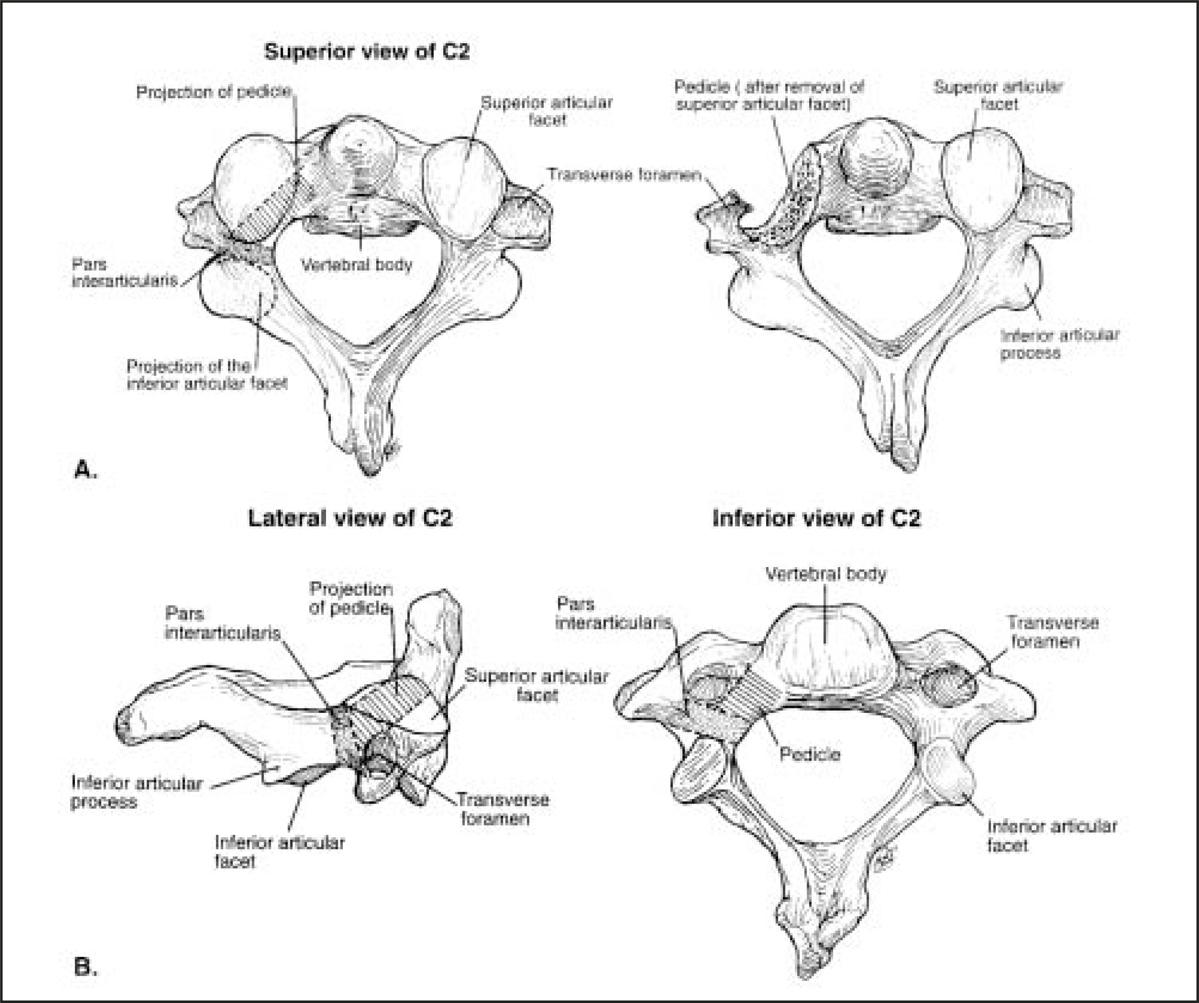
Fractures of the C2 neural arch (ring)
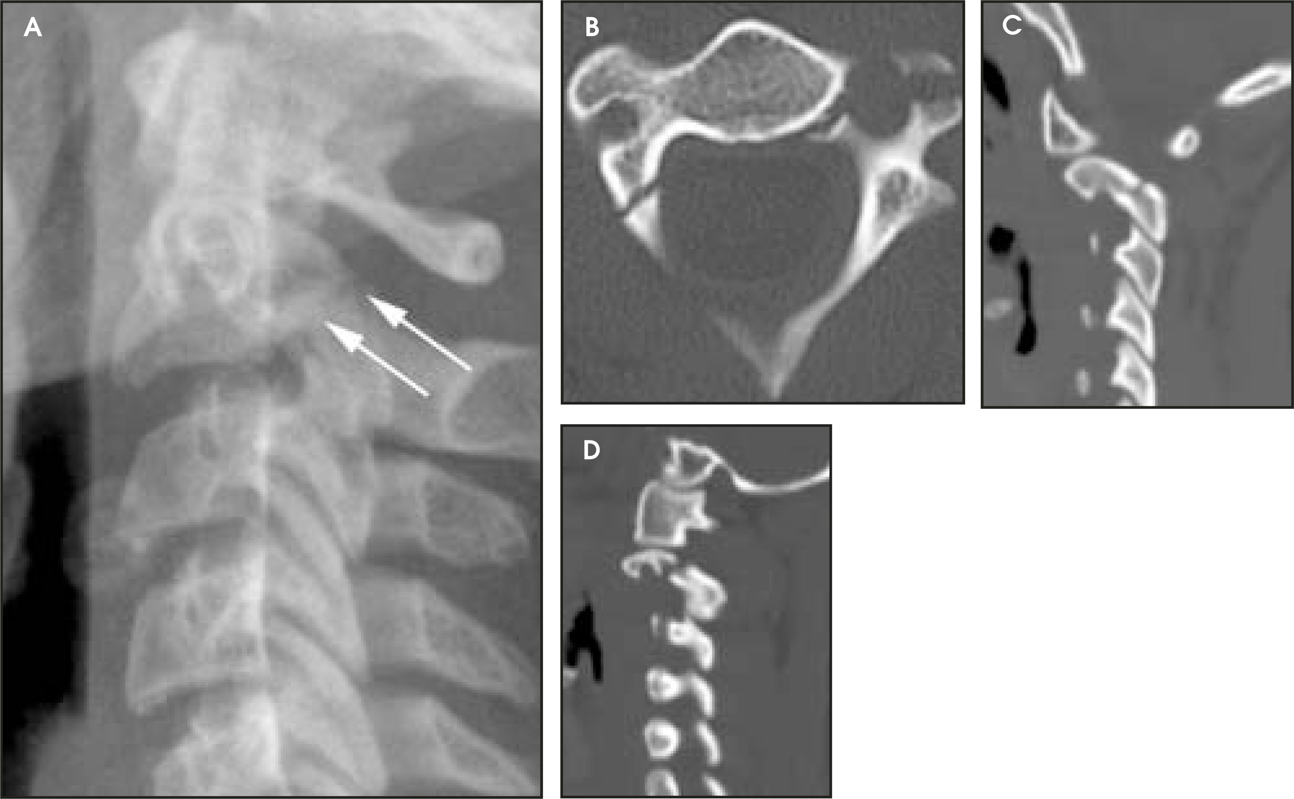
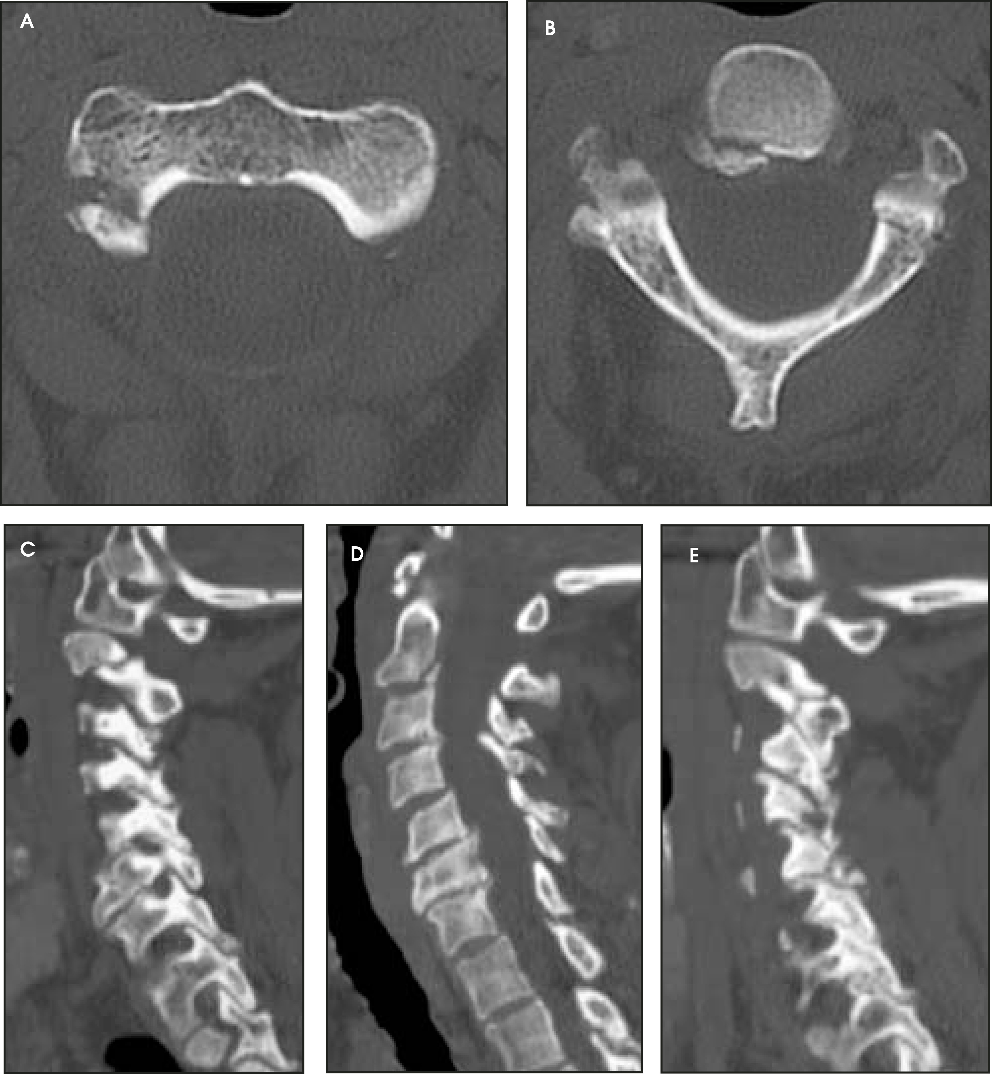
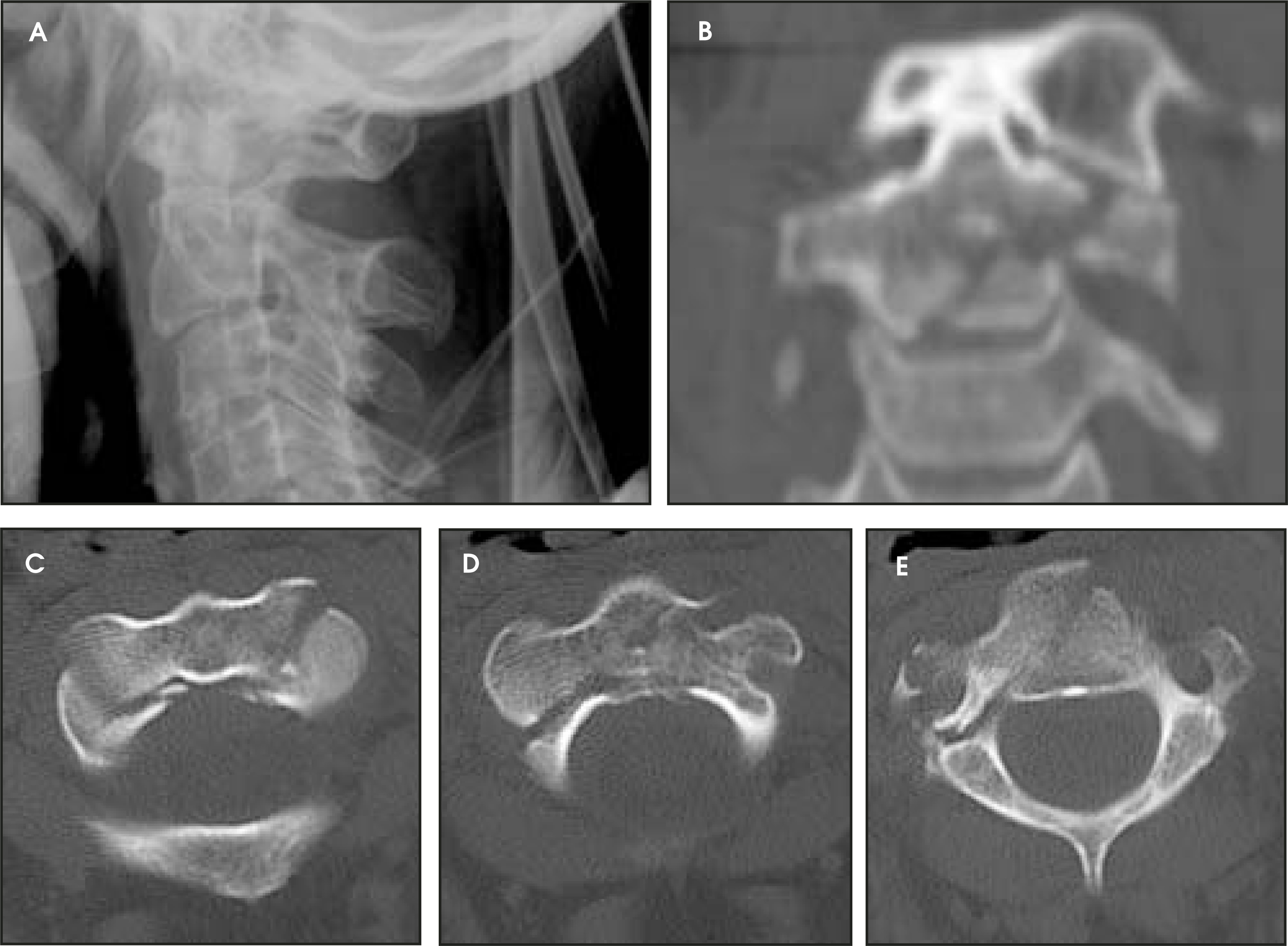
In 1981, Effendi and colleagues4 published a classification scheme inclusive of all fractures of the axis neural arch. Effendi I injuries are “isolated hairline fractures of the ring of the axis with minimal displacement of the body of C2. The fracture line is then oblique, usually involving one or, rarely, both posteroinferior corners of the body”4 (Figure 2). There is no disruption of the C2/C3 intervertebral disc (Figure 3). Effendi II injuries have similar fractures of the C2 ring but are distinguished from type I injuries by “an abnormal disc below the axis.”4 Type II injuries have “3 mm or more of anterior translation and significant angulation at the C2–C3 intervertebral disc space.”5 “The body of the axis may be displaced in fiexion (Figure 4), extension, or obvious forward listhesis”4 (Figure 5). Effendi III injuries were originally defined as “displacement of the anterior fragment, with the body of the axis in the fiexed position; but in addition, the facet joints at C2–C3 are dislocated and locked”4 (Figure 6). Currently, the definition has been broadened to include unilateral or bilateral subluxation or dislocation of the C2–C3 facet joints6 (Figure 7).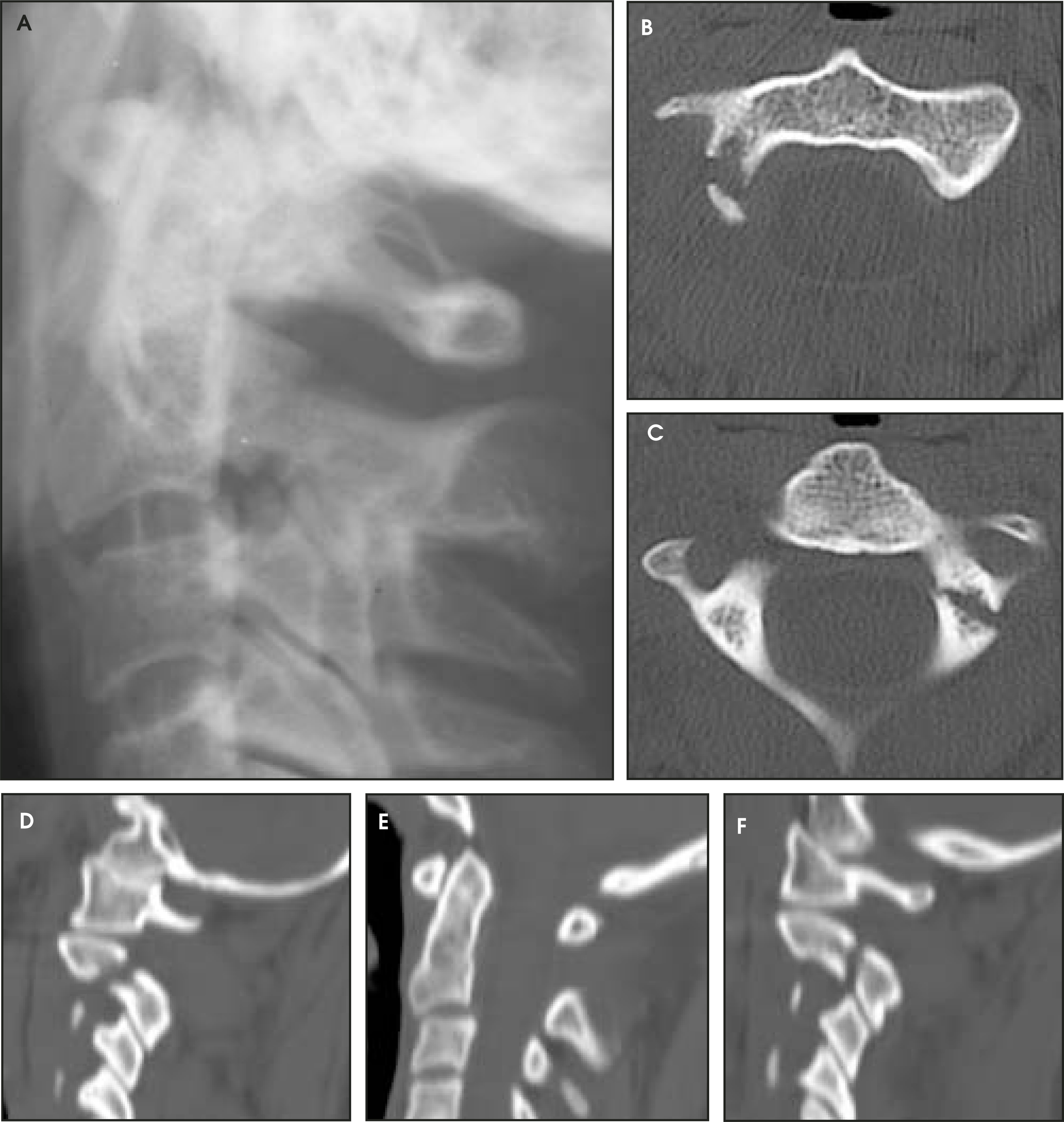
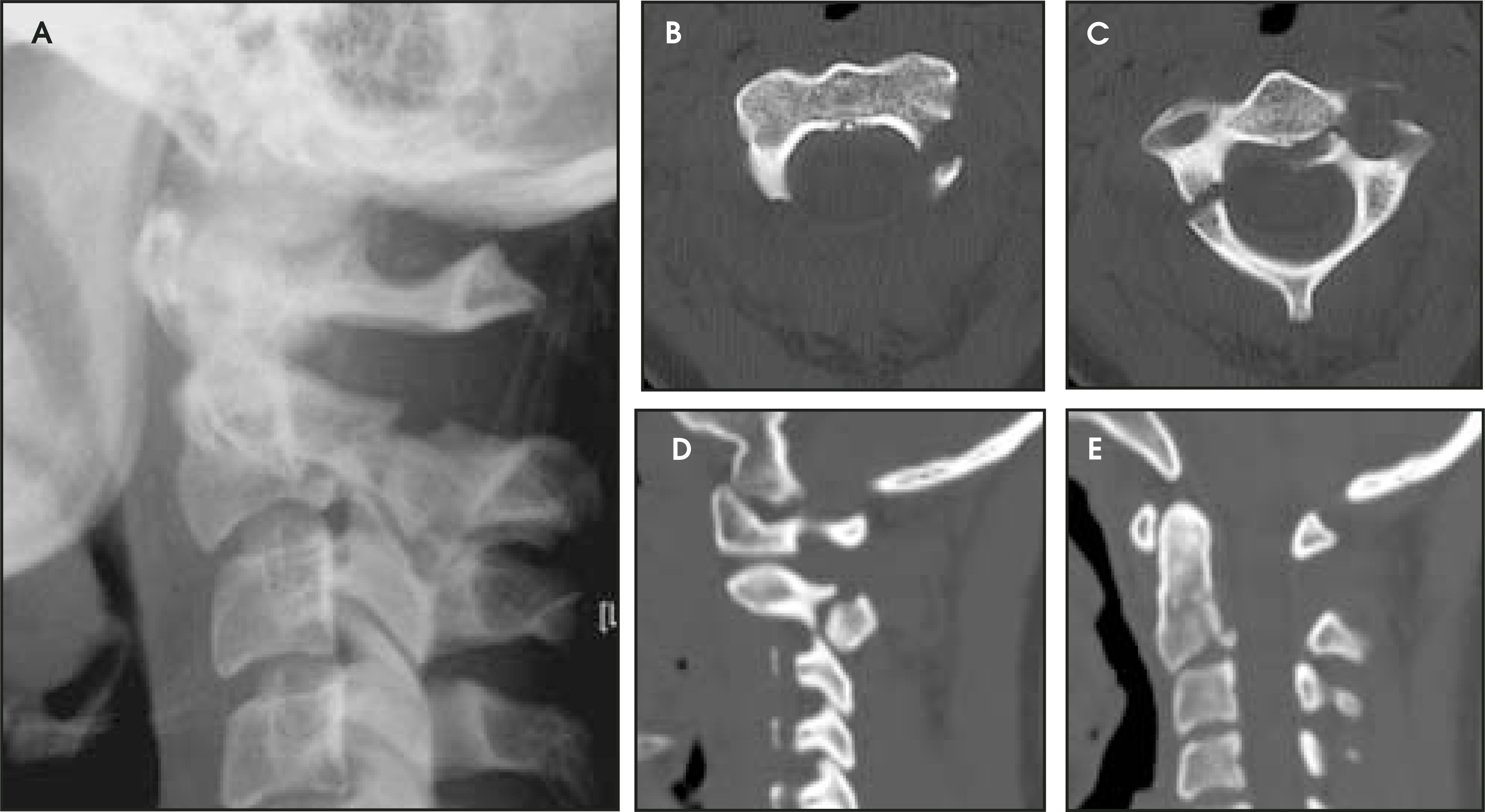
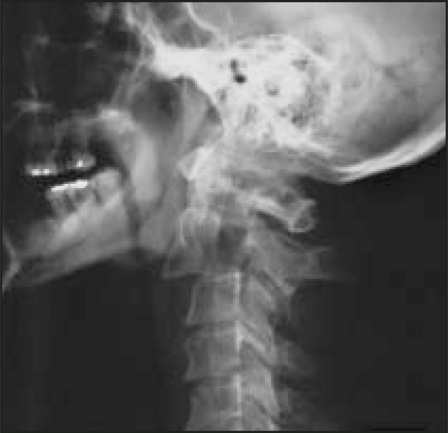
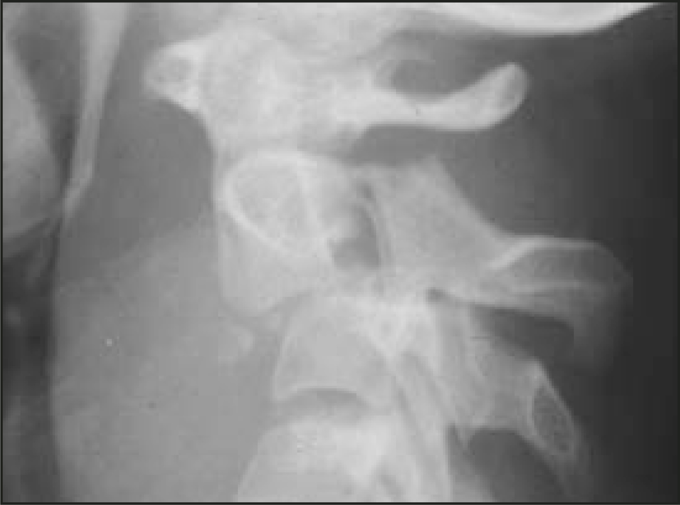
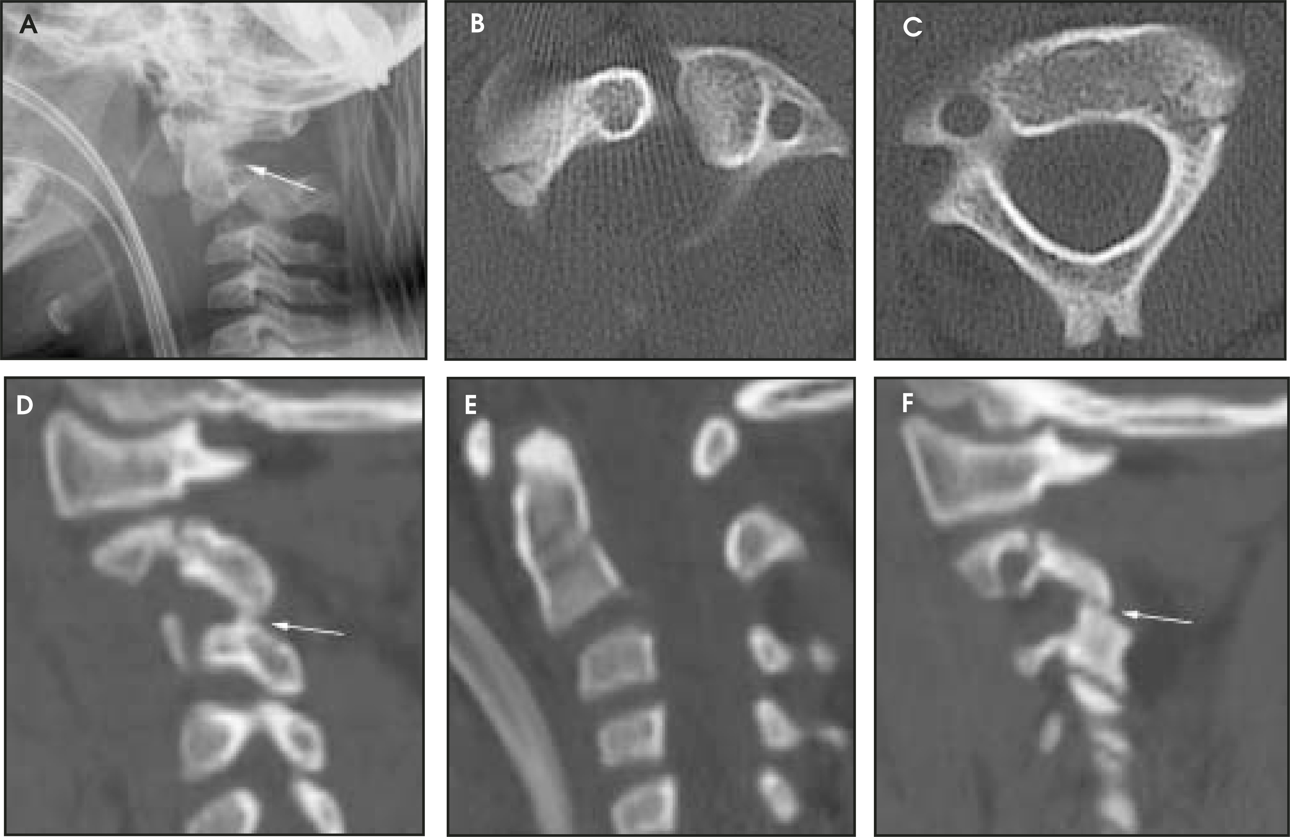
The strength of Effendi’s classification system is that it includes all fractures of the C2 neural arch (or ring). Effendi recognized that fractures of the C2 ring are almost always bilateral but are frequently asymmetrical.4 Indeed, fractures involving the laminae are easily classified using the Effendi system (Figure 8).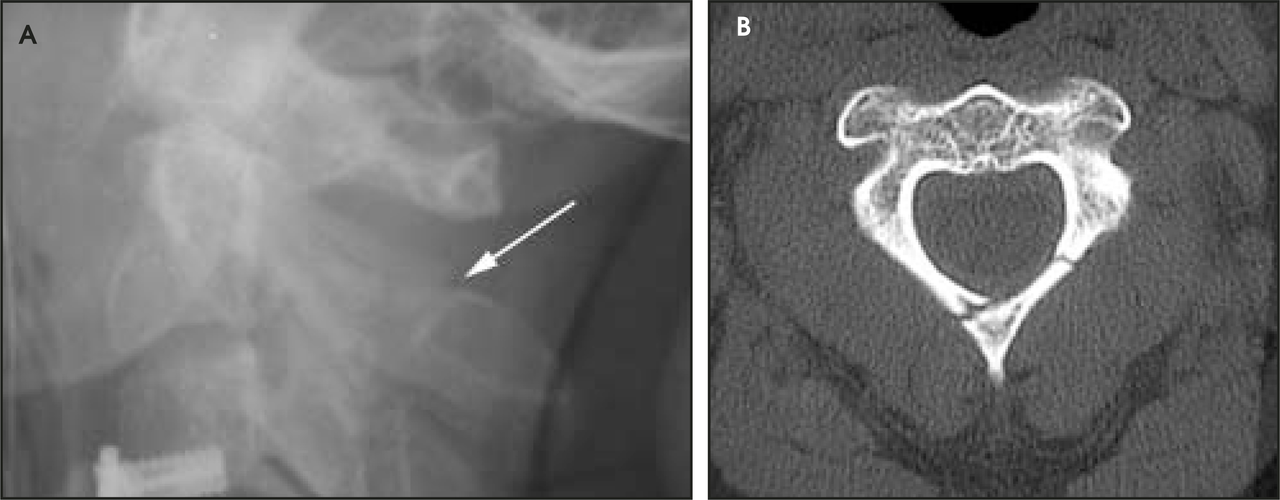
Because the Effendi system is simple and inclusive, it necessarily describes injuries resulting from differing force vectors. As a result, fractures with differing positions and orientations all fall within this system.
Traumatic spondylolisthesis
In order to create more homogenous injury patterns, a subset of C2 neural arch fractures are known as traumatic spondylolisthesis, which is defined as bilateral fracture of the pars interarticularis of C2 or of the adjacent portion of either the superior or inferior articular facet7 (Figure 9). The mechanisms causing TS vary but most frequently are hyperextension combined with axial loading, or fiexion combined with axial load-ing.5,8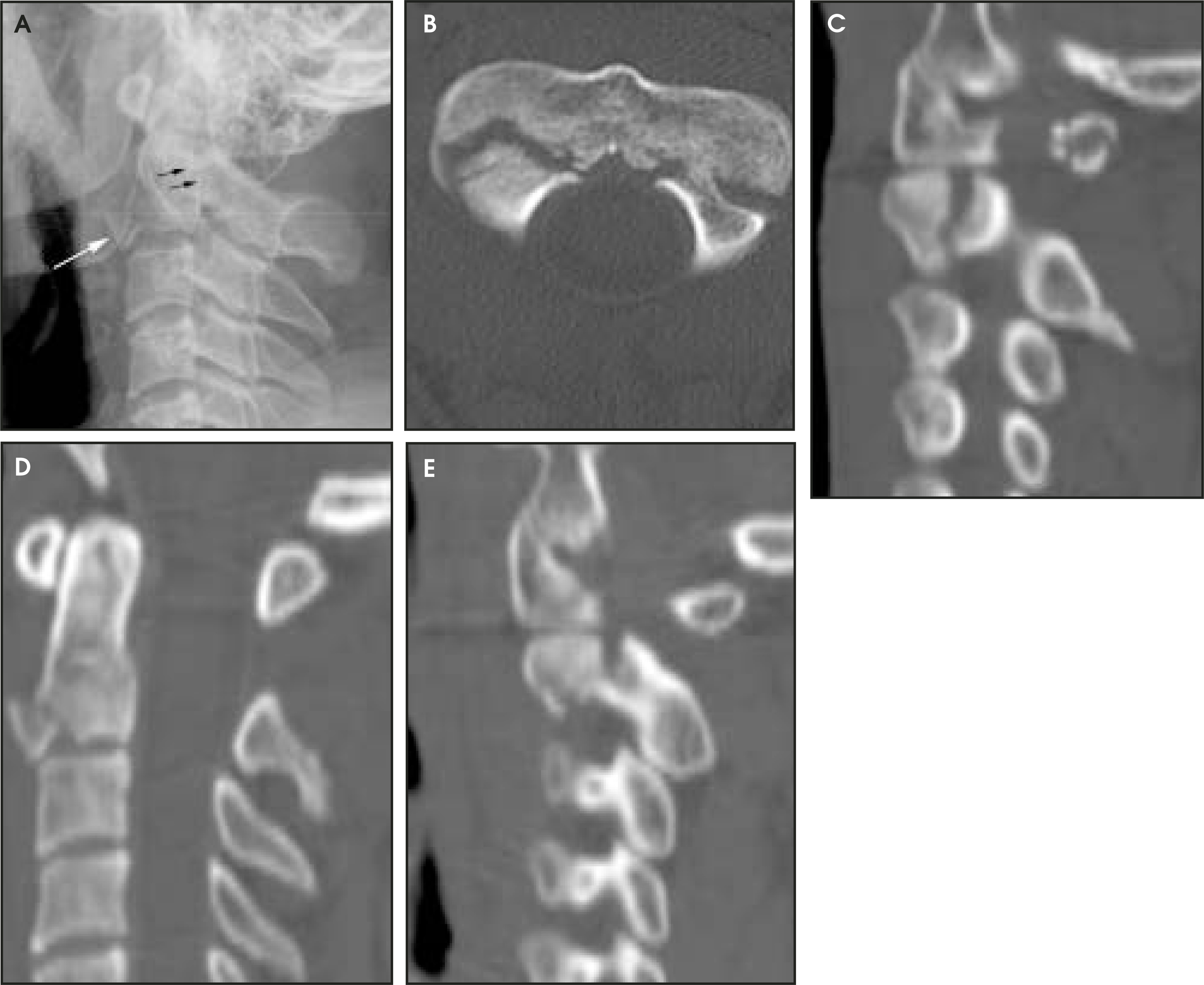
Many authors use the term hangman’s fracture interchangeably with TS, which is incorrect. While the fractures produced by judicial hanging are similar to those seen in TS, judicial hanging is caused by “hyperextension combined with sudden violent distraction,”9 and the differing injury mechanisms distinguish the two.8 At Memorial Hermann Hospital in Houston, TX, our colleagues in Emergency Medicine and Trauma Surgery often order C-spine radiographs and CT scans in victims of suicidal hanging, presumably to identify hangman’s fractures. We have never encountered an actual cervical spine fracture in this setting. Others report a similar lack of clinical utility when imaging victims of suicidal hanging.10,11 To avoid confusion regarding the mechanism of injury in suicidal hanging, we recommend abandoning use of the colorful term hangman’s fracture when referring to TS and other nonjudicial fractures of the C2 neural arch.
Special categories of traumatic spondylolisthesis
Review of the literature reveals inconsistent use of the terms atypical and type A as subcategories of TS. In 1985, Levine and Edwards5 expanded upon the Effendi classification scheme by including a subclass of injuries that they referred to as Type IIa. These injuries had the features of an Effendi Type II with severe angulation, but minimal or no anterior translation. They found that the addition of therapeutic traction to patients with this injury resulted in distraction at the C2–C3 intervertebral disc space (Figure 10).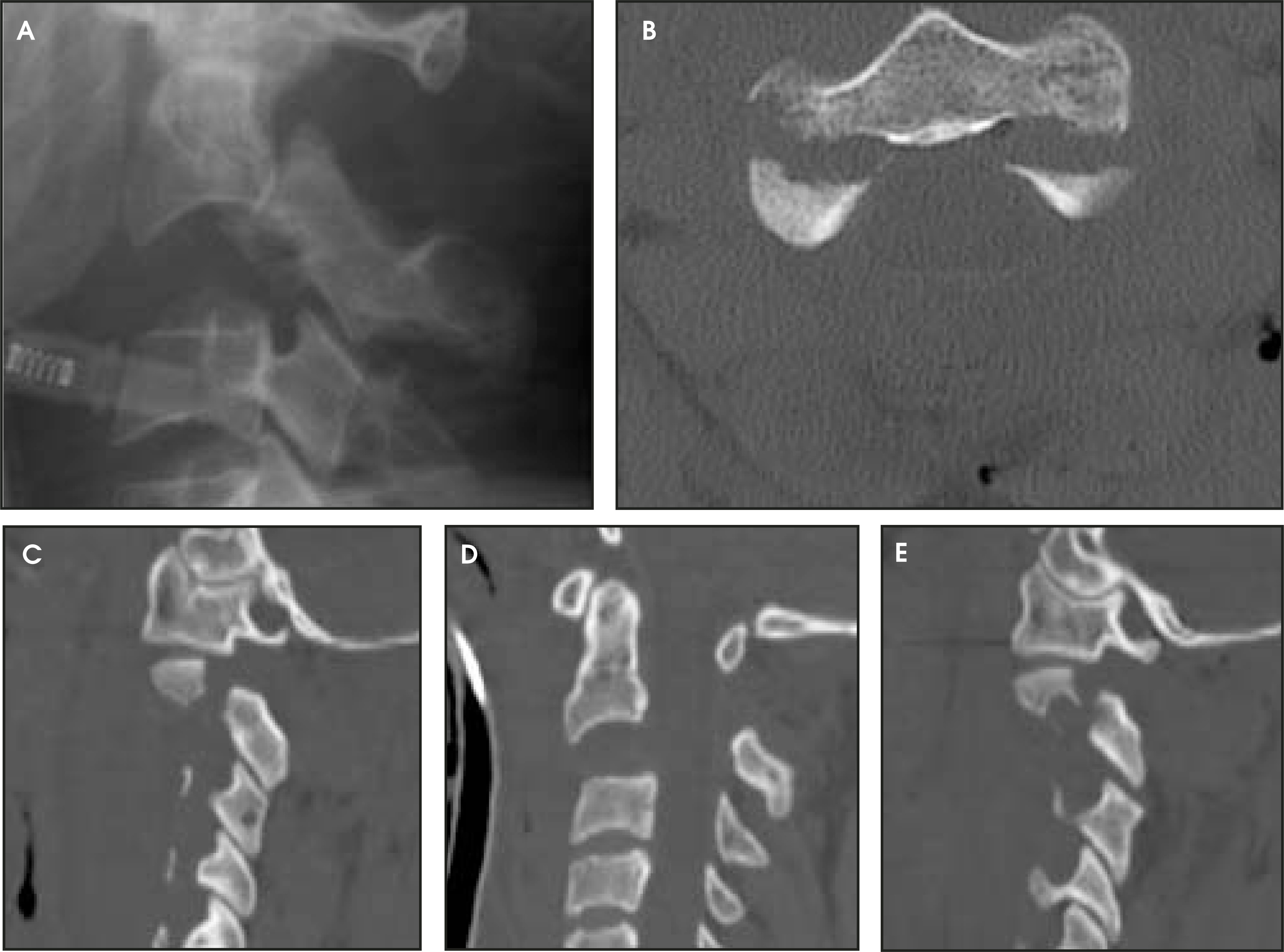
Atypical traumatic spondylolisthesis (ATS) is another variant of TS in which fracture lines extend from the pars interarticularis into the posterior portion of the body of C2.7 These obliquely oriented fractures create fragments of the inferoposterior vertebral body. If the neural arch displaces posteriorly, as occurs with type II injuries, this posterior body fragment may narrow the spinal canal and cause spinal cord injury (Figure 11).12 In contrast, typical TS usually results in expansion of the vertebral canal and has low propensity for spinal cord injury.13,14 In our opinion, the atypical type I (or Ia) classification is not particularly important because there is no translation, and therefore no therapeutic implication (Figure 12). The terms Ia, IIa, and atypical have been used interchangeably in the literature, but in our interpretation they actually represent distinct patterns of injury.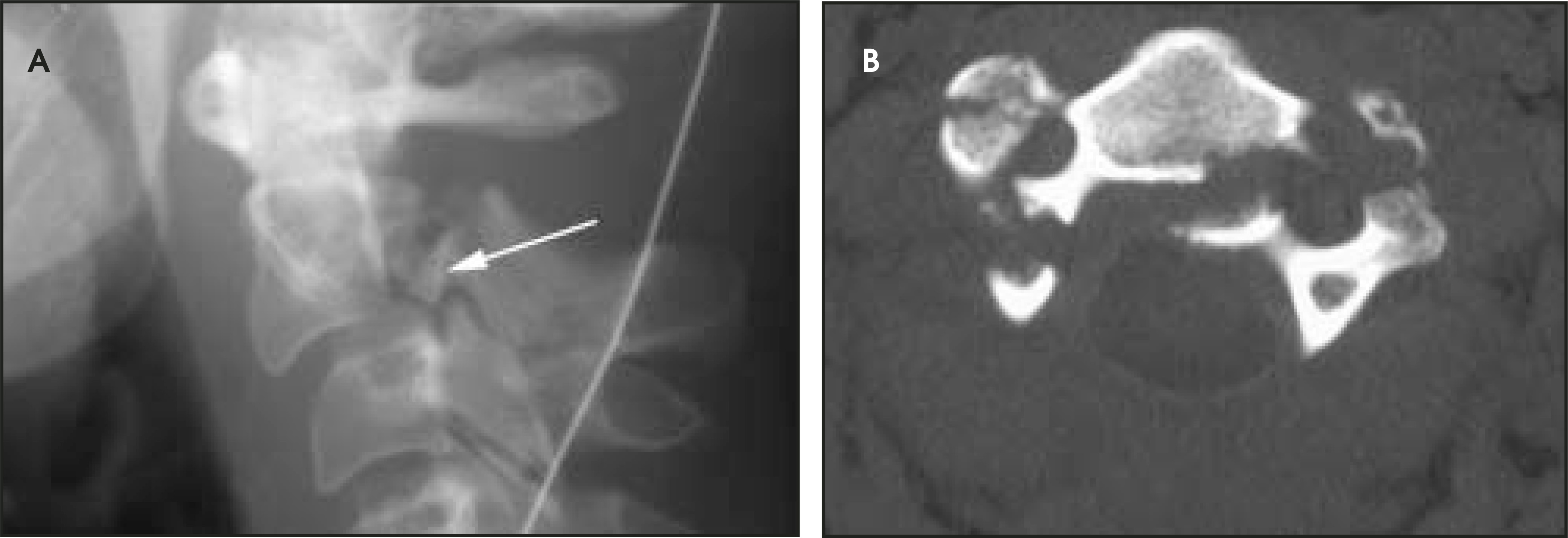
C2 body fractures—The fat C2 sign
Obliquely oriented fractures through the body of C2 (dens type III, ATS, and comminuted fractures) can result in anterior and/or posterior displacement of the axis body fragments.15 On lateral radiographs, this produces an apparent increase in the distance between the anterior and posterior body margins of C2 compared with C3, which is called the “fat C2” sign (Figure 13). It is important to recognize a “fat C2” because the actual fracture line may not be visible on the lateral radiograph. The fat C2 sign indicates a potentially unstable injury and mandates further diagnostic imaging studies. Coronally oriented fractures through the posterior aspect of the C2 vertebral body occur through a zone of trabecular rarefaction, which contributes to C2 fractures in elderly individuals.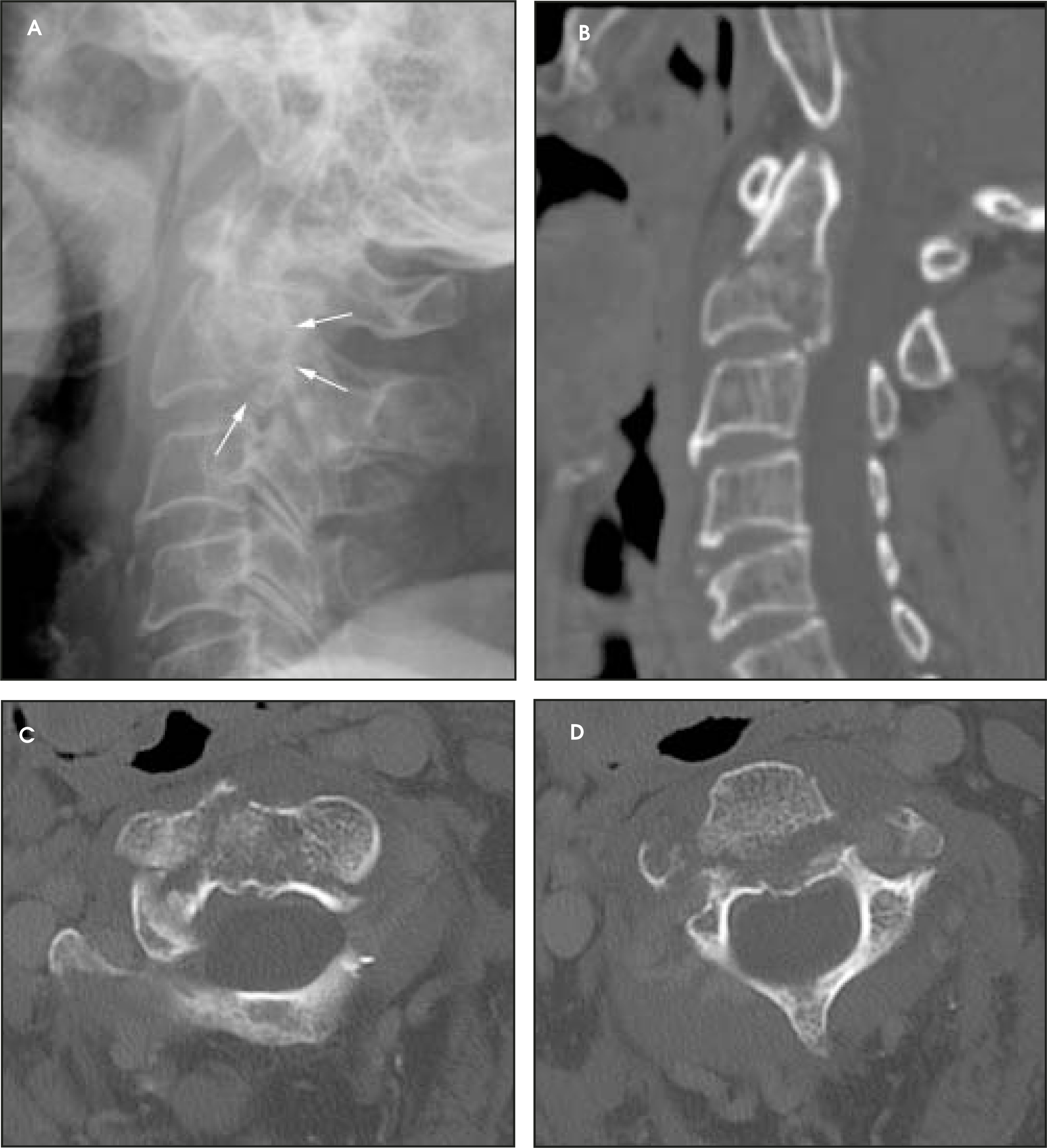
C2 body fractures—Hyperextension teardrop fractures
Hyperextension teardrop fractures of the axis are the result of traction from the anterior longitudinal ligament on its insertion at the anteroinferior portion of the C2 body during sudden, violent extension.7 The resultant fracture produces a wedge-shaped piece of avulsed bone (Figures 9 and 14). In elderly patients with osteoporotic bones and inelastic soft tissues, even less violent forces can cause these fractures and may produce little or no prevertebral soft-tissue swelling.7 In younger patients, the presence of hyperextension teardrop fractures usually indicates that there has been tremendous force involved, and therefore, marked soft-tissue swelling is usually noted.7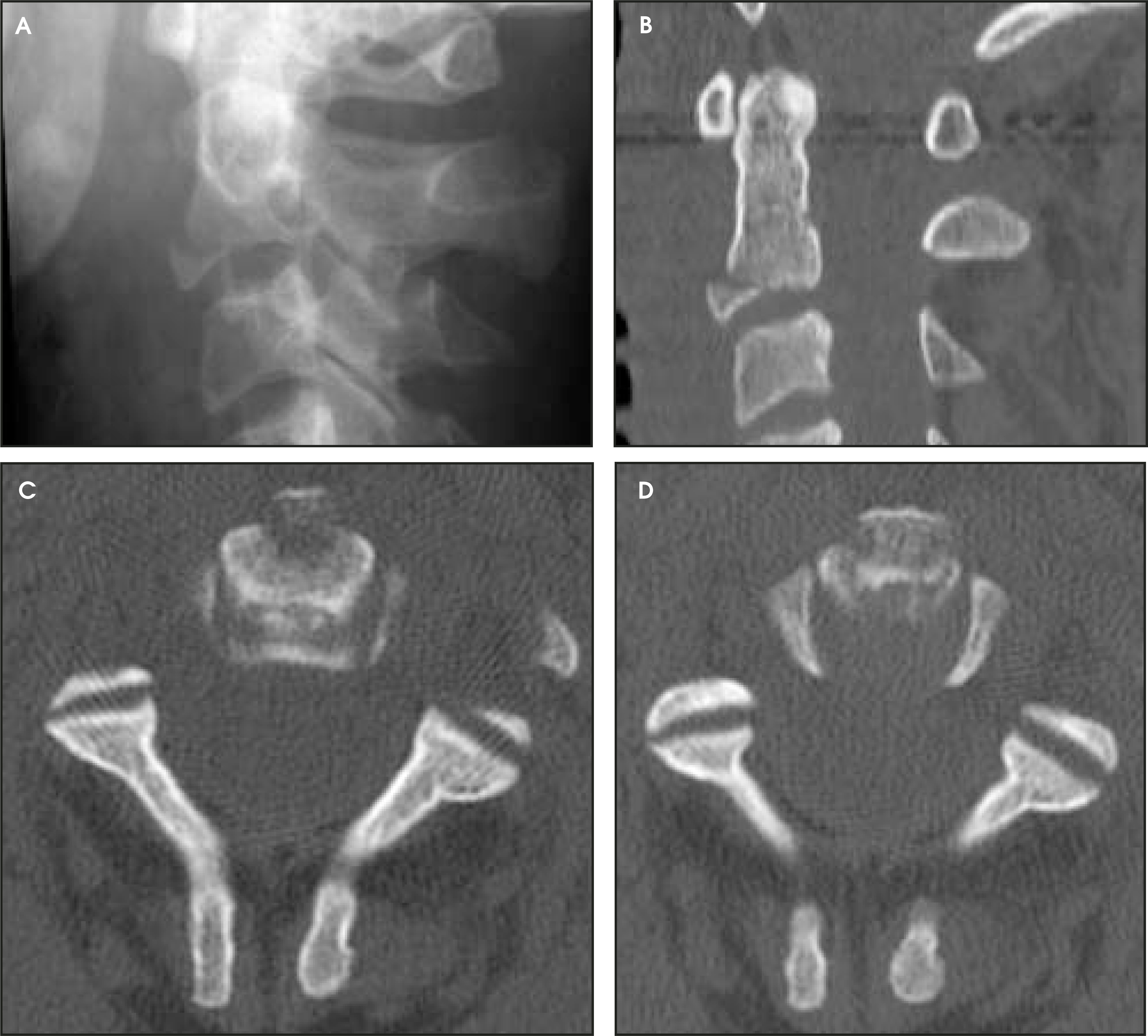
C2 body fractures—Classification scheme
Compared with dens fractures and fractures of the C2 neural arch (TS and other types), fractures of the C2 body are uncommon. Fujimura and colleagues16 have devised a classification scheme based on 31 cases collected over a 26-year period. Type I is an avulsion fracture identical to the hyperextension teardrop fracture described above (Figures 9 and 14). Type II is a transverse fracture running horizontally through the C2 vertebral body caudal to the superior end of the atlantoaxial joint (Figure 15). The fracture line is caudal to that in the type III dens fracture. Type III is a burst fracture, or comminuted fracture of the C2 body with multiple fragments dislocated anteroposteriorly, often with retropulsion into the spinal canal. Traumatic spondylolisthesis is present in all cases (Figure 13). Type IV is a sagittal or parasagittal fracture extending from a point lateral to the dens vertically or diagonally to the inferior surface of C2 (Figure 16).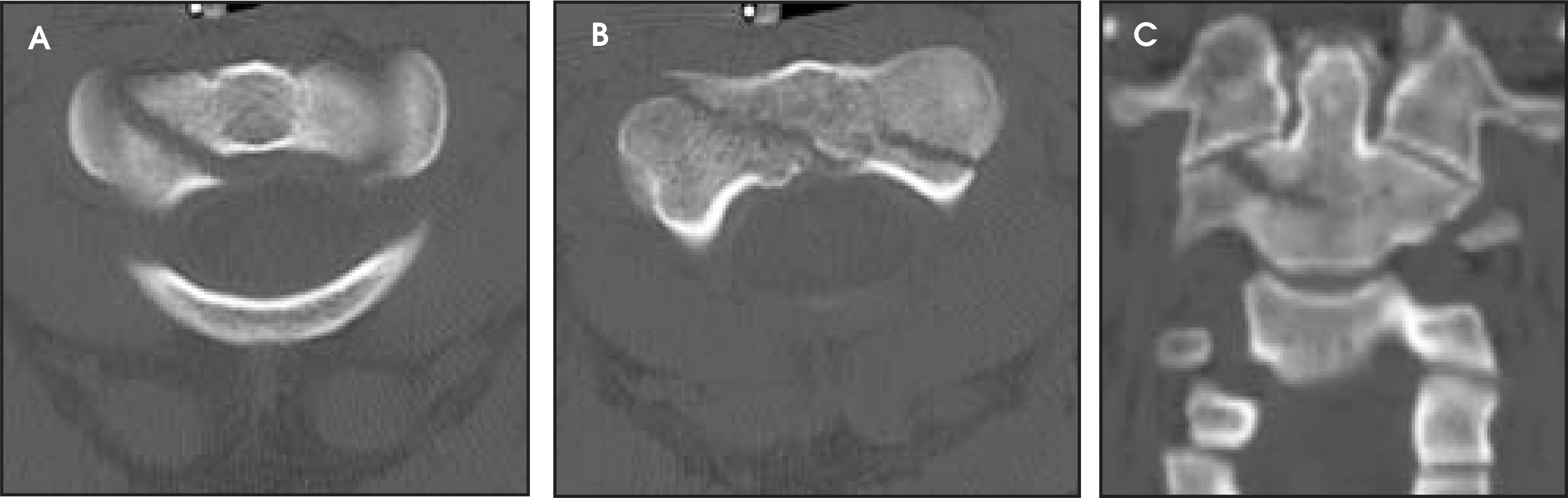
C2 lateral mass fractures
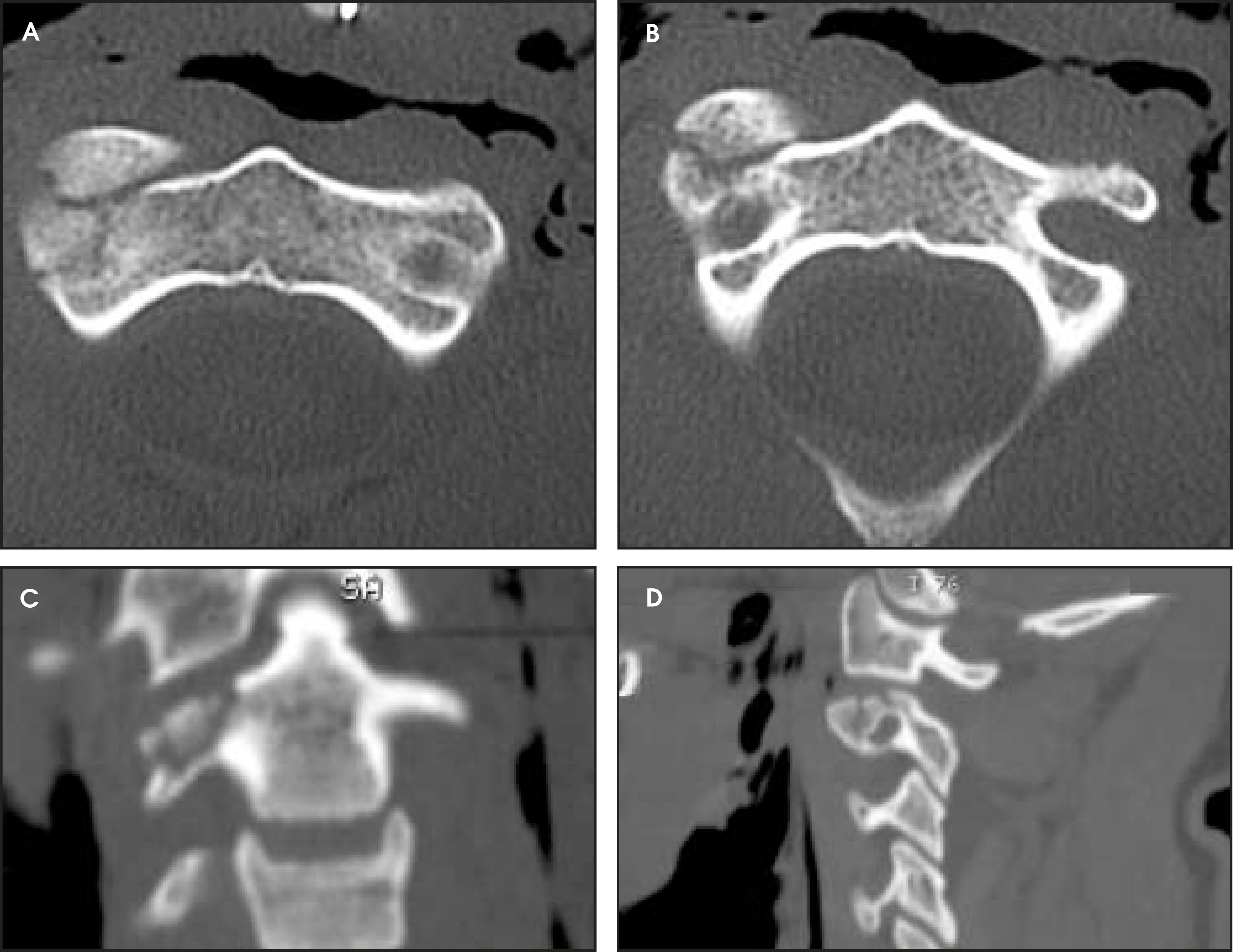
Fractures of the C2 lateral mass run the spectrum from small hairline fractures with no displacement (Figure 17), to grossly comminuted, depressed fractures with significant displacement (Figure 18).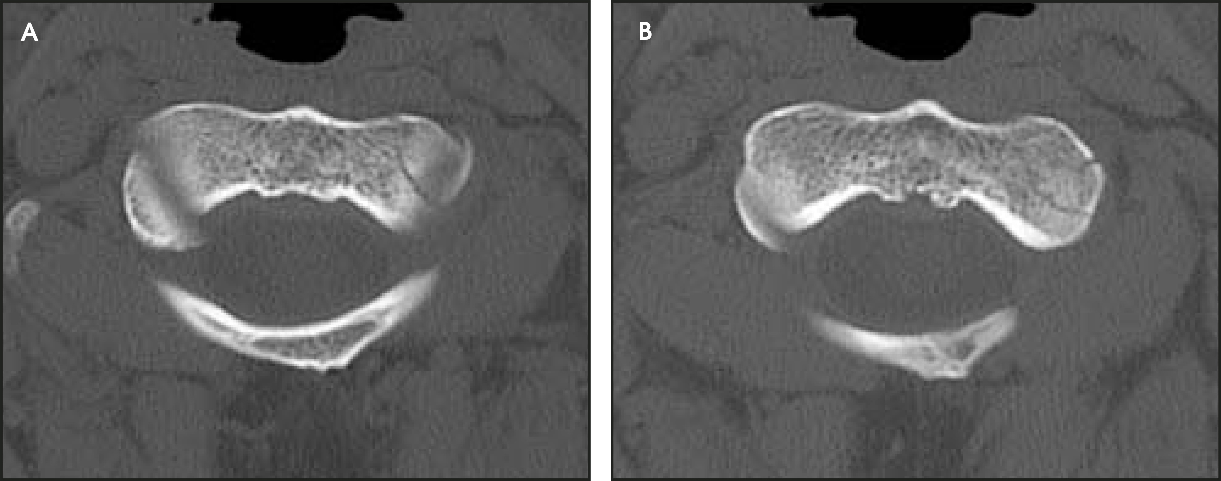
Conclusion
After studying cases of nonodontoid axis fractures in this pictorial essay, several important factors regarding fractures of the neural arch of C2 should be clear. The following are most important:
- 1)
Traumatic spondylolisthesis involves the pars interarticularis. Fracture of the pedicle of C2 should be considered a separate entity.
- 2)
Look for ≥3 mm of displacement at the C2–C3 interface, indicating an Effendi II fracture.
- 3)
Identify distraction, subluxation, or dislocation of one or both the facet joints of C2–C3, as seen in an Effendi III fracture.
- 4)
If a posterior fragment of the vertebral body is identified and compromises the spinal canal, the diagnosis of “atypical TS” is applicable and the spinal cord may be at risk.
- 5)
Paradoxical widening of the C2–C3 intervertebral disc or increasing angulation of the C2 body fragment on images obtained after application of traction indicates a Type IIa fracture.
- 6)
A triangular fragment of the vertebral body indicates a hyperextension teardrop fracture.
- 7)
A “fat C2” sign indicates a comminuted fracture of the vertebral body.
References
- West O. Imaging of upper cervical spine injuries—Part I: C0–C1. Appl Radiol. 2002;31(2):23-32.
- West O, Bilow R, Jarolimek A. Imaging of upper cervical spine injuries—Part II: The dens. Appl Radiol. 2003;32(2):30-38.
- Ebraheim N, Fow J, Xu R, Yeasting R. The location of the pedicle and pars interarticularis in the axis. Spine. 2001;26.
- Effendi B, Roy D, Cornish B. Fractures of the ring of the axis. A classification based on the analy-sis of 131 cases. J Bone Joint Surg Br. 1981;63-B:319-327.
- Levine A, Edwards C. The management of traumatic spondylolisthesis of the axis. J Bone Joint Surg Am. 1985;67:217-226.
- Levine A, Clark C, Ducker T, Dvorak J. The Cervical Spine. 1998:429-449.
- Burke J, Harris J. Acute injuries of the axis vertebra. Skeletal Radiol. 1989;18:335-346.
- Francis W, Fielding J, Hawkins R. Traumatic spondylolisthesis of the axis. J Bone Joint Surg Br. 1981;63-B:313-318.
- Wood-Jones F. The ideal lesion produced by judicial hanging. Lancet. 1913;1:53.
- Kalita J, Mishra V, Misra U, Gupta R. Clinicoradiological observation in three patients with suicidal hanging. J Neurol Sci. 2002;198:21-24.
- Penney D, Stewart A, Parr M. Prognostic outcome indicators following hanging injuries. Resuscitation. 2002;54:27-29.
- Starr J, Eismont F. Atypical hangman’s fractures. Spine. 1993;18:1954-1957.
- Schneider R, Livingston K, Cave A, Hamilton G. “Hangman’s fracture” of the cervical spine. J Neurosurg. 1965;22:141-154.
- Hadley M, Browner C, Sonntag V. Axis fractures: A comprehensive review of management and treatment in 107 cases. Neurosurgery. 1985;17:281-290.
- Pellei D. The fat C2 sign. Radiology. 2000;217:359-360.
- Fujimura Y, Nishi Y, Kobayashi K. Classification and treatment of axis body fractures. J Orthop Trauma. 1996;10:536-540.
Citation
. Imaging of upper cervical spine injuries – Part III: C2 below the dens. Applied Radiology. 2004;33(7):9-21. doi:10.37549/AR1266.