Imaging of upper cervical spine injuries—Part I: C0–C1
Applied Radiology — Vol. 31 , Issue 2 , pp. 23 -32
DOI: 10.37549/AR1076
Published: February 1, 2002
Categories
Pictorial essays often have strict limits on the number of cases and the number of pictures in each case. Subtleties of diagnosis may be lost if insufficient axial computed tomography (CT) images are presented because of editorial limits. Variations from patient-to-patient in the appearance of injuries may be lost due to fiscal necessities of the journal. In failing to present cases in sufficient number or in sufficient detail, the author may create the false impression that all cases are “classic” or “typical.” This article and the series that will follow in subsequent issues of Applied Radiology will not suffer from a lack of sufficient illustration. The theme of these articles will be “Few words, many pictures.”
This series will emphasize the radiography and CT of spine injuries with the depth and breadth rarely possible in print media. To achieve this goal, each article will focus on a small group of spine injuries. The series will be organized using a cranial-caudal approach, beginning with the upper cervical spine. Where appropriate, injuries in a given anatomic region will be subcategorized into pathomechanical families.
The upper cervical spine includes the skull base (C0), the atlas vertebra (C1), the axis vertebra (C2), and the associated joints. In contrast to the remainder of the spine, the upper cervical region does not have a repetitive, segmental pattern. Tracing a series of lines through the upper cervical region is of little value. Instead, the radiologist must look for each of the major injuries and exclude their presence. The unique anatomy of this region requires careful inspection, since several injuries are subtle on radiographs or CT.
The terminology and classification scheme used in this article is based on that advocated by the Cervical Spine Research Society.1
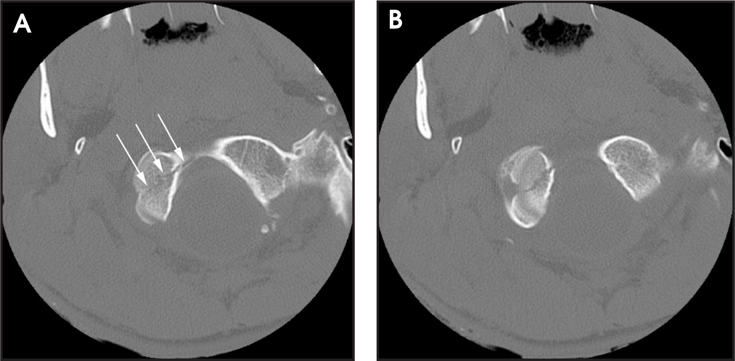
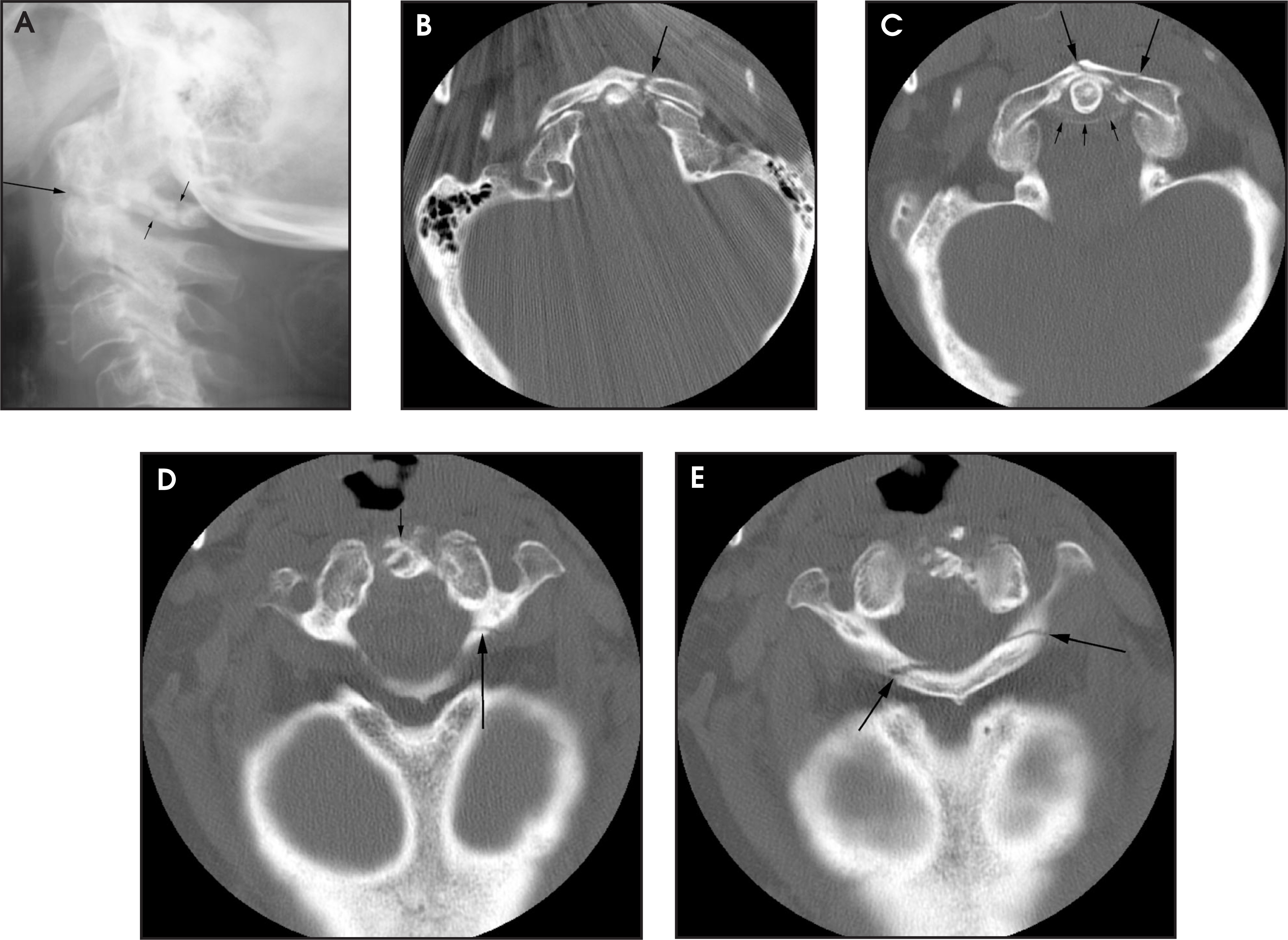
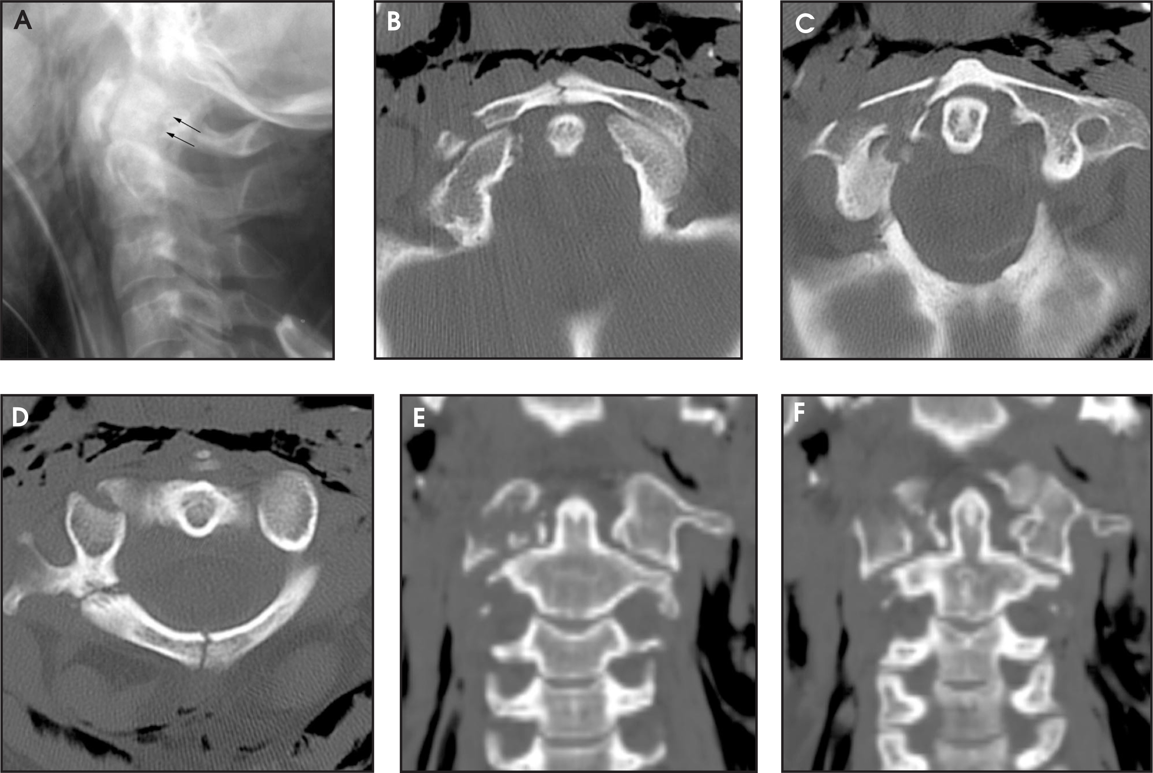
Occipital condyle fractures are not frequently visualized on radiographs, but are readily visible on CT of the head or upper cervical spine performed for suspected head or spine injury. The type I fracture is a comminuted impaction fracture of the occipital condyle that results from a direct blow to the head and is a stable injury (figure 1).2 The type II fracture represents extension of an occipital bone fracture into the occipital condyle. Like type I, the type II fracture is the result of a blow to the head and is stable unless the entire condyle is separated from the skull base (figure 2). The type III fracture is a wedge-shaped avulsion fracture of the transverse alar ligaments on the medial aspect of the occipital condyles and is frequently associated with occipitocervical instability (figure 3). Thin-section (1 to 1.5 mm) CT with sagittal and coronal reformatted images is required to assess for malalignment.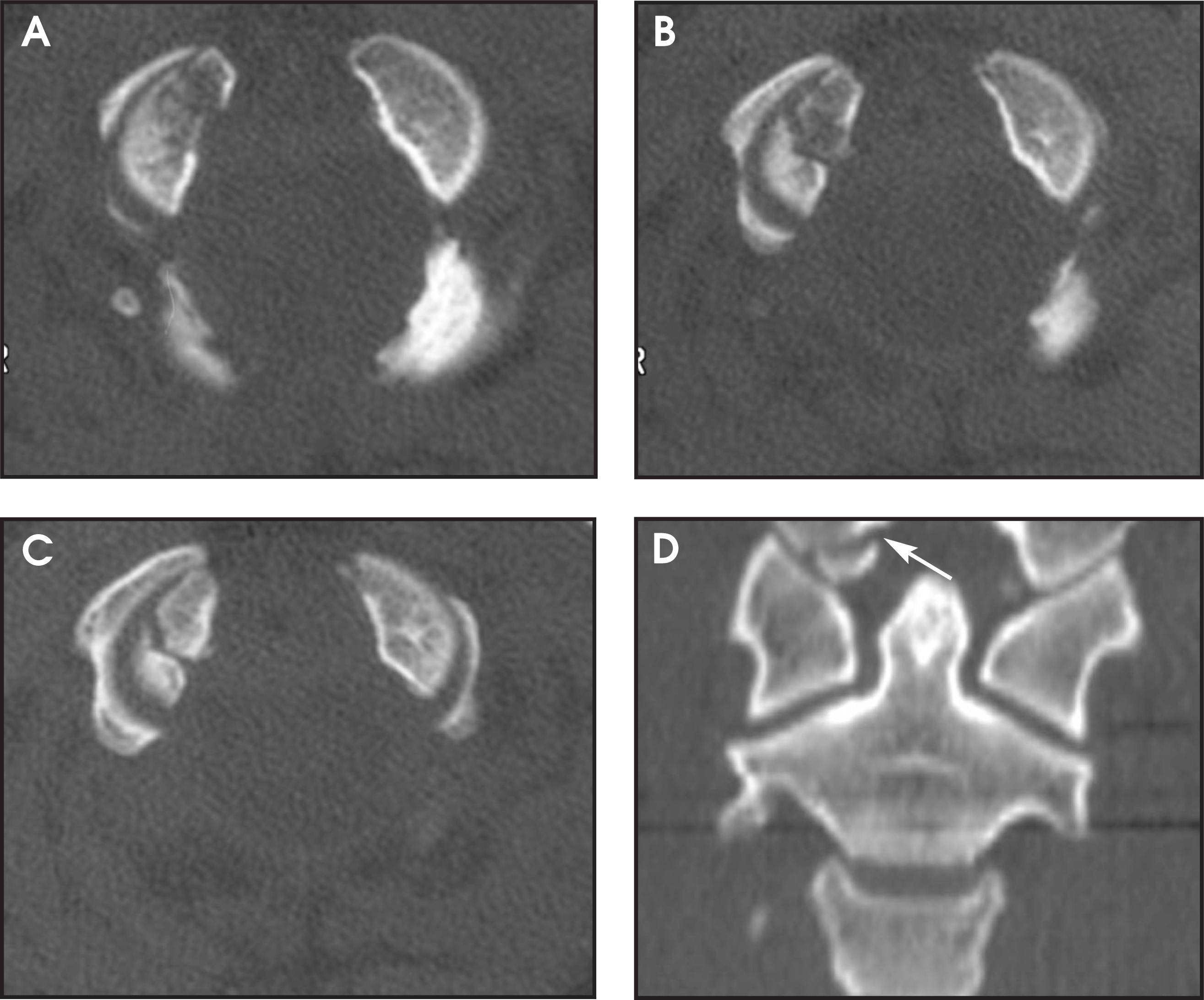
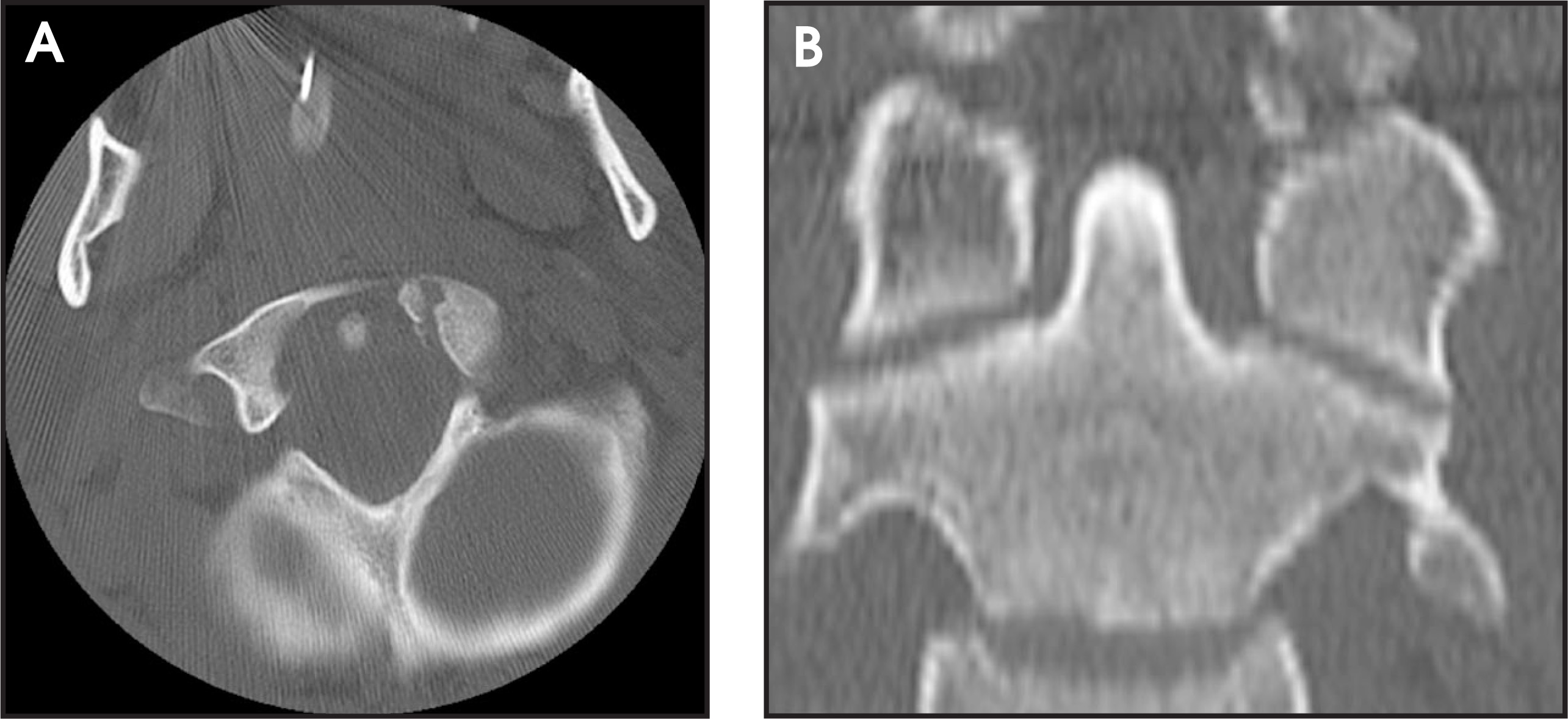
Occipitocervical subluxation or dislocation is occasionally survivable, particularly in children.3 On radiographs, occipitocervical malalignment may be recognized by identification of uncovered occipital condyles (figure 4). Alignment may be assessed qualitatively by comparing the position of the anterior margin of the foramen magnum (the basion) and the posterior margin of the foramen magnum (the opisthion) to the subjacent cervical vertebrae. In a normal individual, the basion should be positioned over the dens and the opisthion should fall along the curved spinolaminar line drawn upward along the spinolaminar junctions of the upper cervical vertebrae. Quantitatively, a diagonal line drawn from the basion to the tip of the dens, the basion-dens interval (BDI) should not exceed 12 mm.4 On thin-section CT, the occipital condyles should reside within the concavities (fossae) of the C2 lateral masses. The joint space should be no more than 2 mm wide and the articular surfaces should be parallel.2 The relationship between the basion and the dens is well seen on sagittal reformatted views; again, the basion-dens interval should not exceed 12 mm.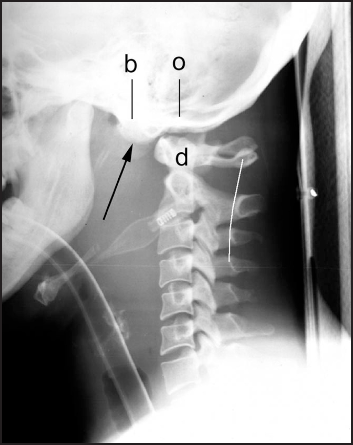
In occipitocervical subluxation or dislocation, the occipito-atlantal are usually both anteriorly translated and distracted. The injury is usually readily apparent on radiographs. Less readily apparent cases have less displacement, either in anterior translation (figure 5) or distraction (figure 6).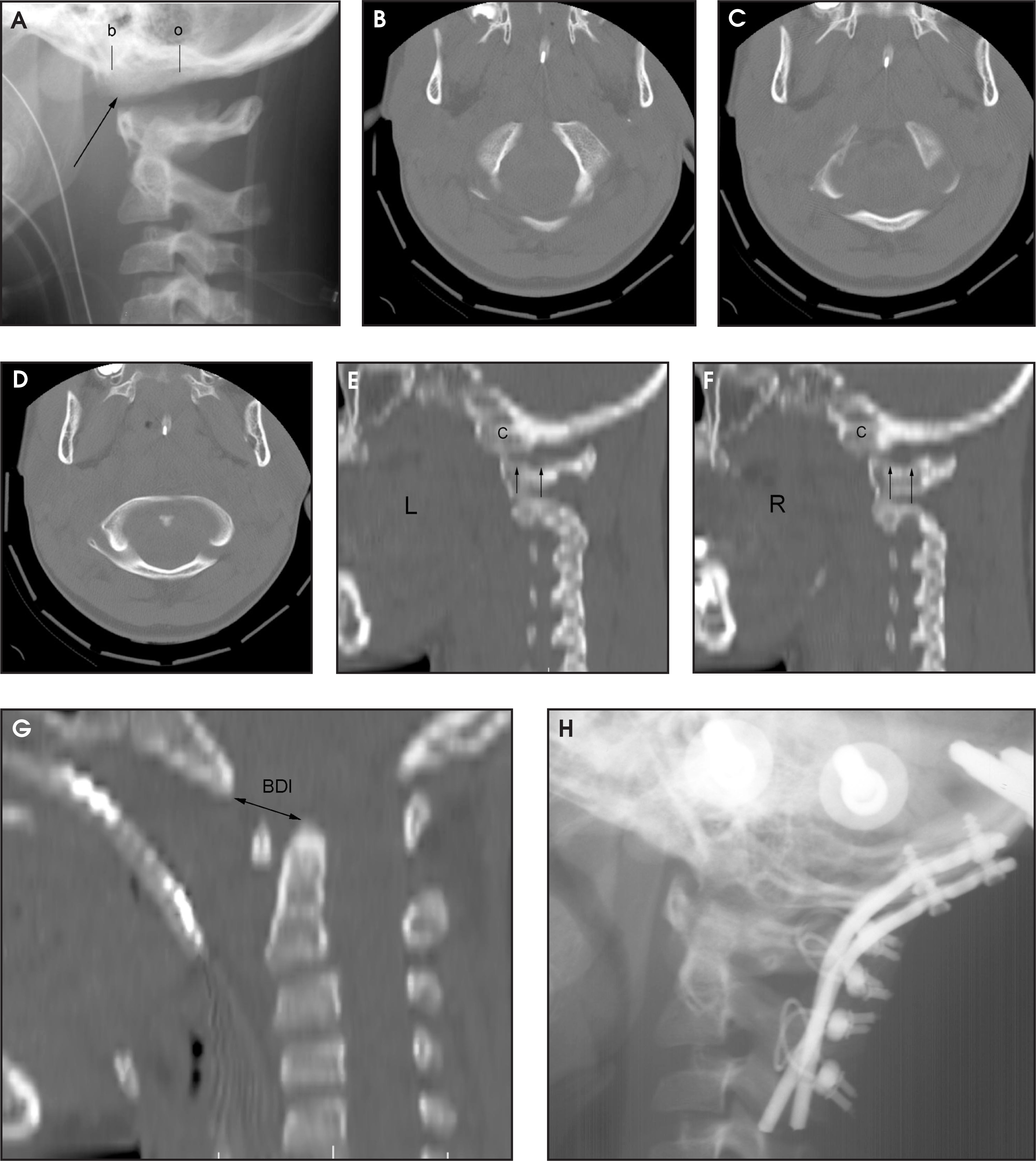
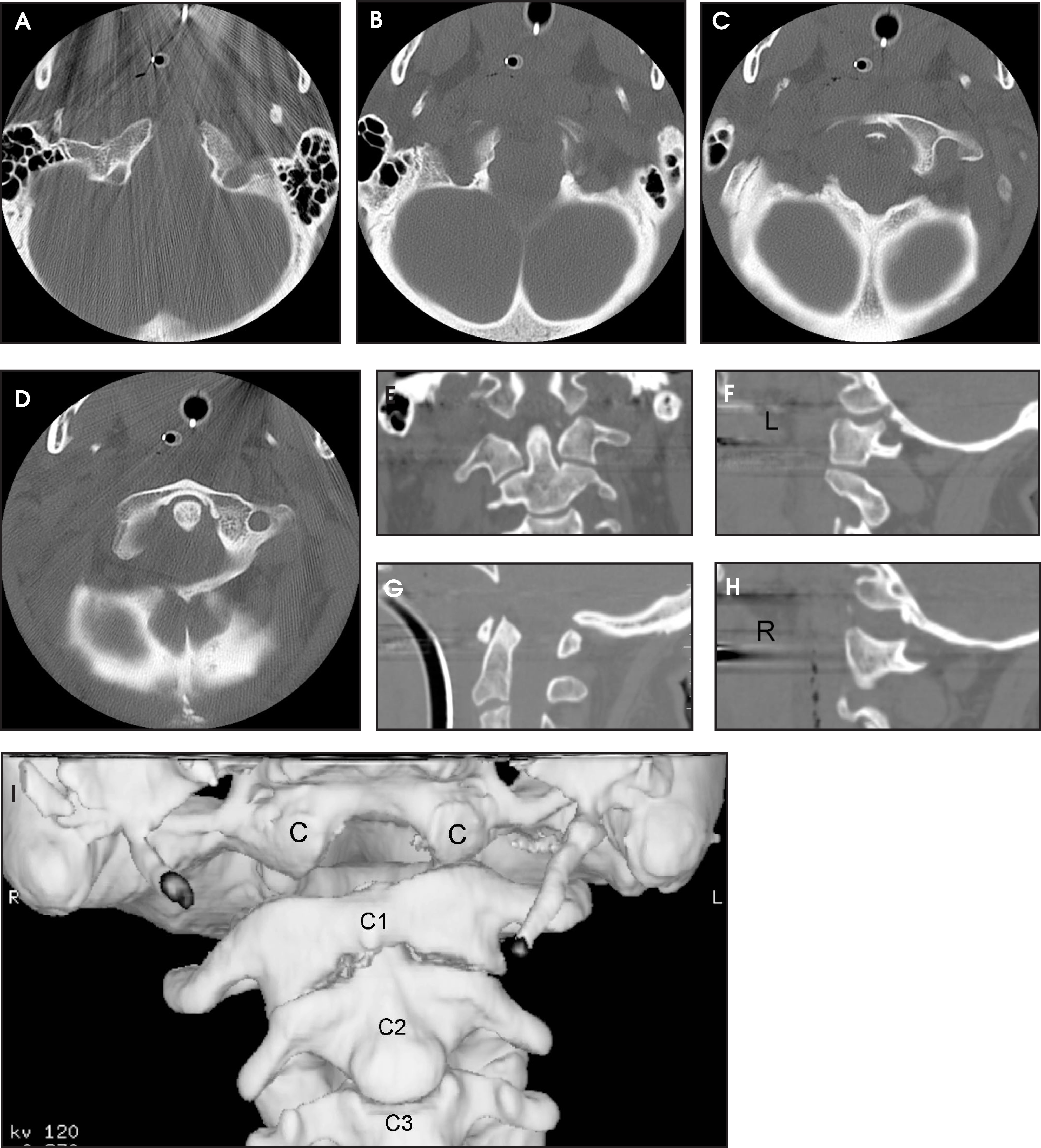
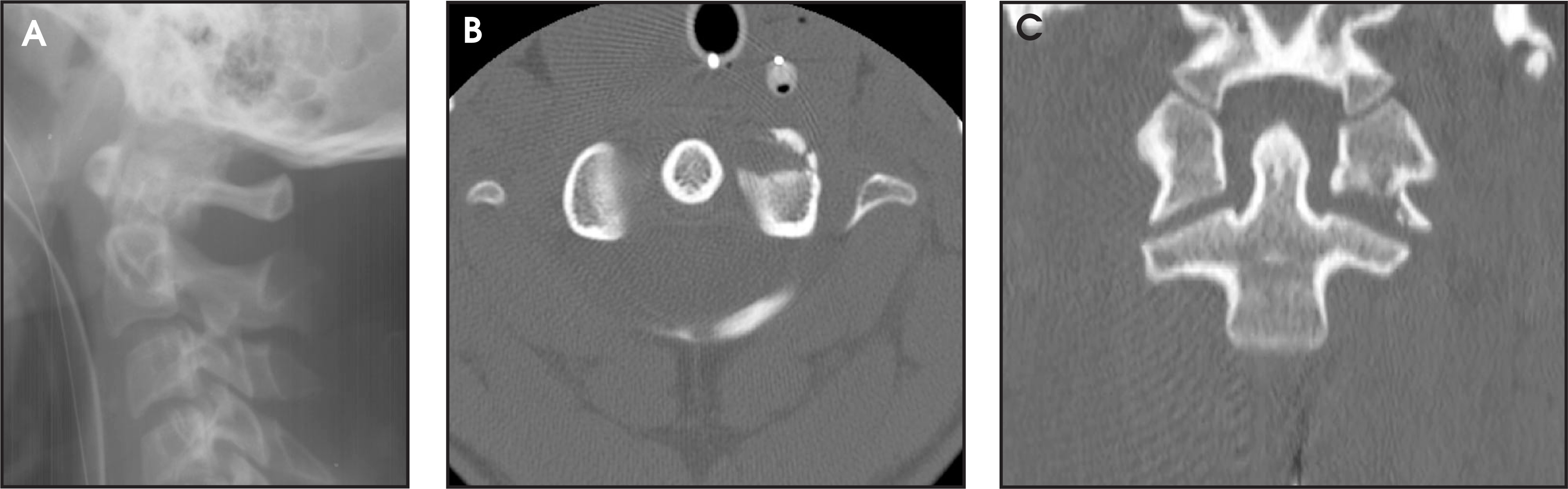
The C1 posterior arch fracture is typically bilateral and results from hyperextension of the upper cervical spine.5 Posterior arch fractures are usually visible on lateral radiographs (figure 7). However, when the fracture is located far laterally at the junction with the lateral mass, the overlying dens or lateral mass often obscures the fracture line (refer to figure 11 for a similar example). Computed tomography detection may be difficult if the scanning plane passes obliquely through the ring of C1. Even if the posterior arch is seen segmentally, fractures may be detected by looking for sharp cortical margins. If 1- to 1.5-mm source axial images are available, axial reformatted images may be made to correct for obliquity, so that the C1 ring may be seen in its entirety on a few contiguous images. These “true axial” reformatted images make evaluation of the C1 ring much easier.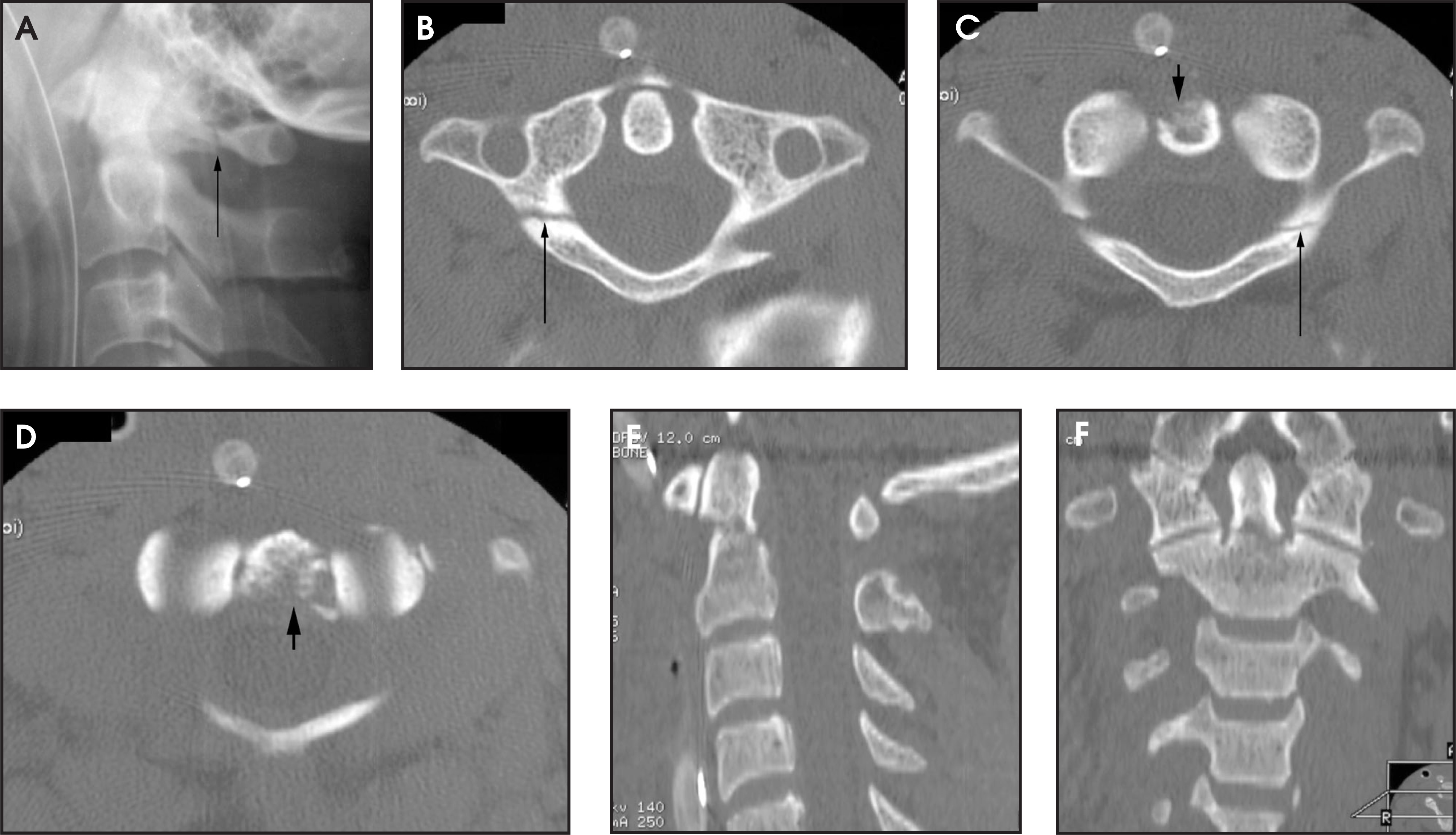
The isolated anterior C1 arch fracture is uncommon (figure 8). It may be distinguished from the much more common congenital midline cleft by recognition of sharp cortical margins indicating fracture.6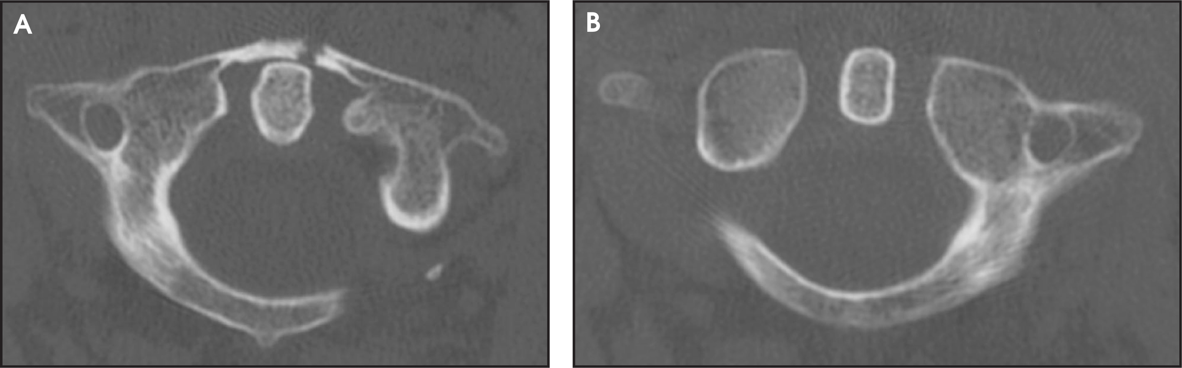
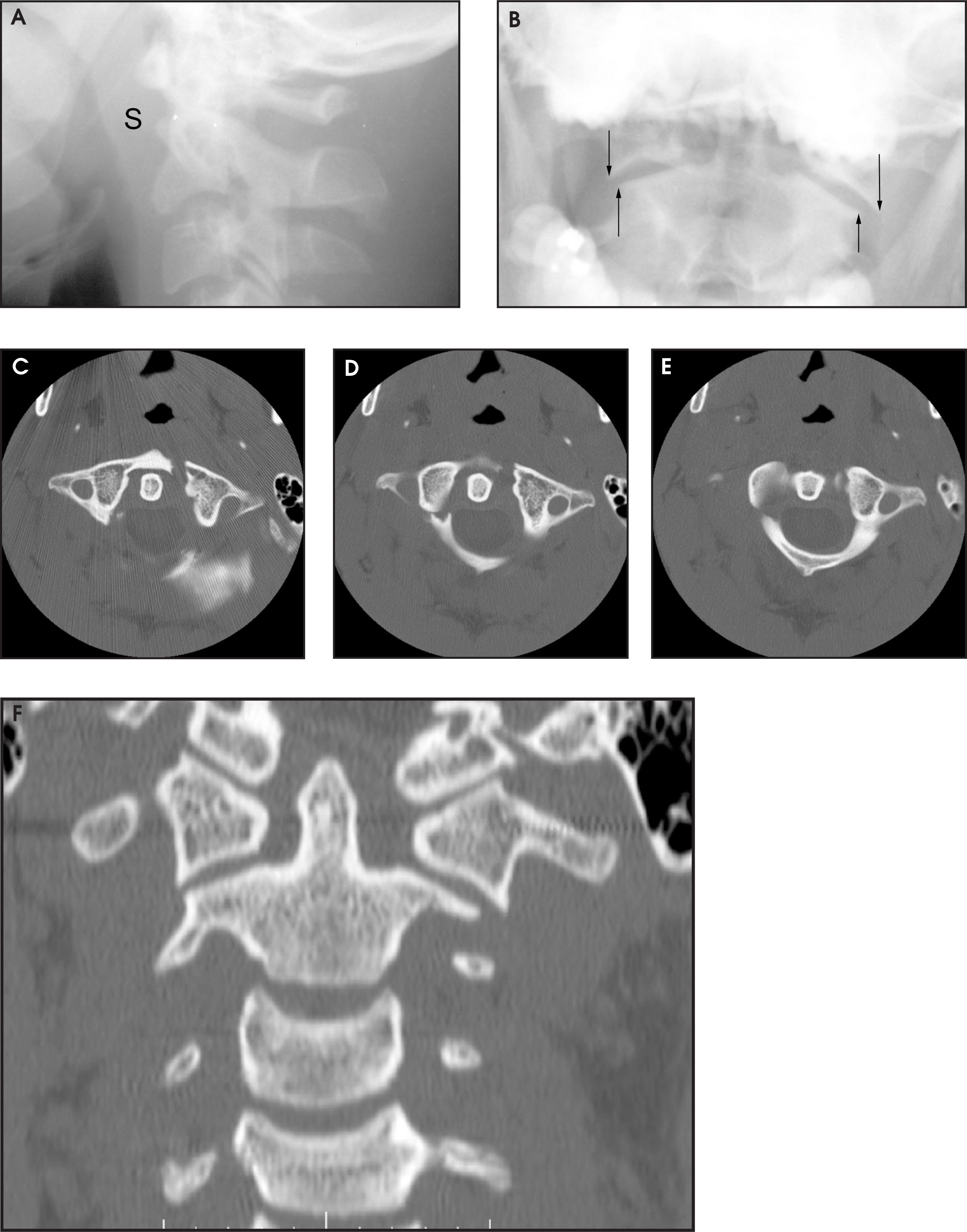
The burst fracture of C1 (Jefferson) is the result of an axial load.5 Two, 3 or 4 fractures are present in the C1 ring, allowing the lateral masses to slide laterally if the fractures are displaced. Radiographic signs include lateral subluxation of one or both of the lateral masses on the open-mouth odontoid view (figure 9). As in posterior arch of C1 fracture, a fracture line through the posterior arch is usually, but not always, visible on the lateral radiograph (figures 10, 11, and 12). Fractures through the anterior and posterior arches of C1 are seen easily on axial CT images. While the 4-part Jefferson bursting fracture with 2 fractures through the anterior arch and 2 fractures through the posterior is considered “classic” or “typical” (figure 10), axial CT frequently reveals variations from the classic pattern (figures 11 and 12). Lateral subluxation of the lateral masses of C1 is readily visible on coronal reformatted images, but may be difficult to recognize on axial images. Subluxation of the lateral masses by more than 7 mm from their expected anatomic position implies disruption of the transverse atlantal ligament.7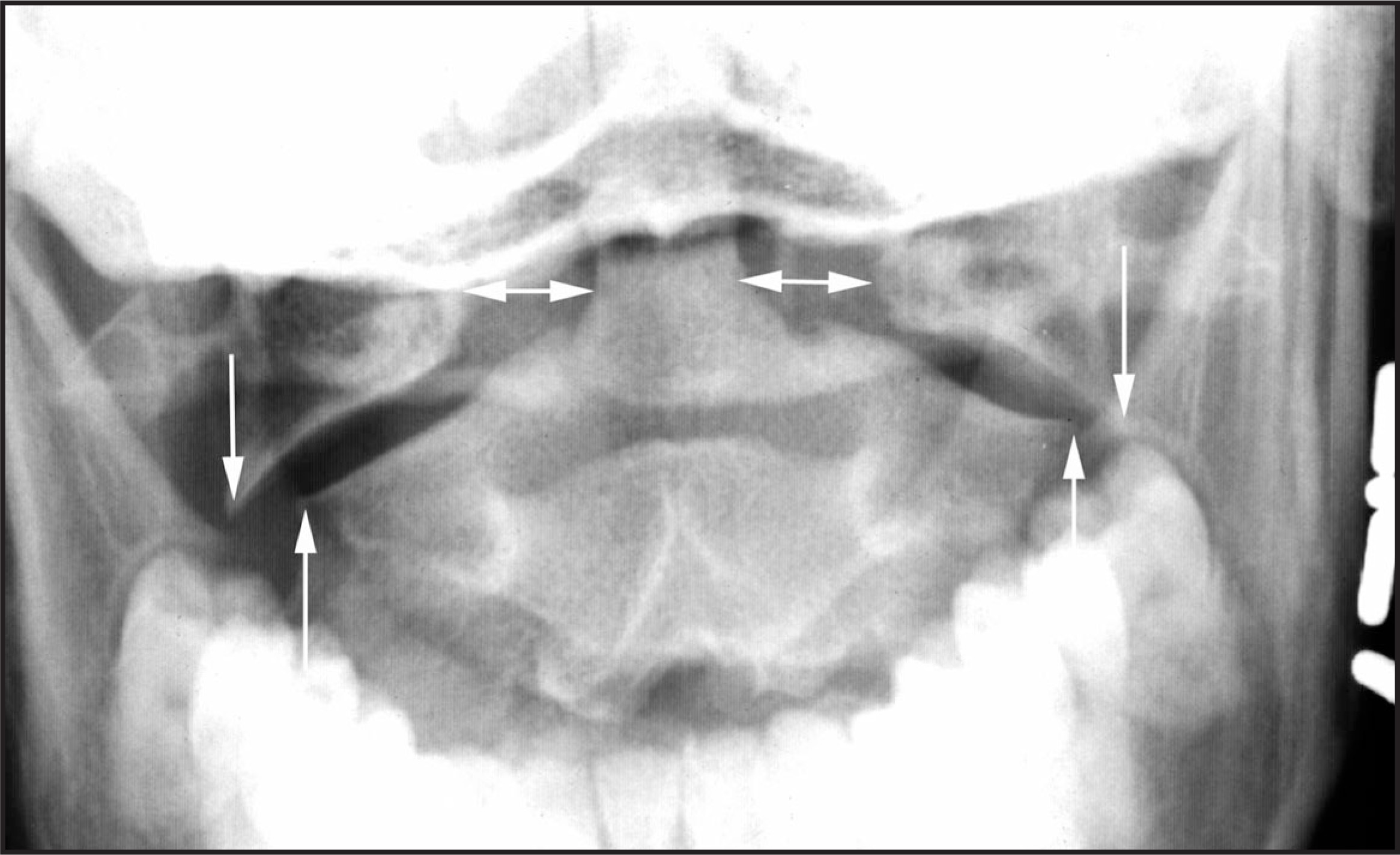
Fracture of the C1 lateral mass is characterized by ipsilateral fractures of the anterior and posterior C1 arch (figure 13). Less commonly, the articular surface of the lateral mass is fractured (figure 14).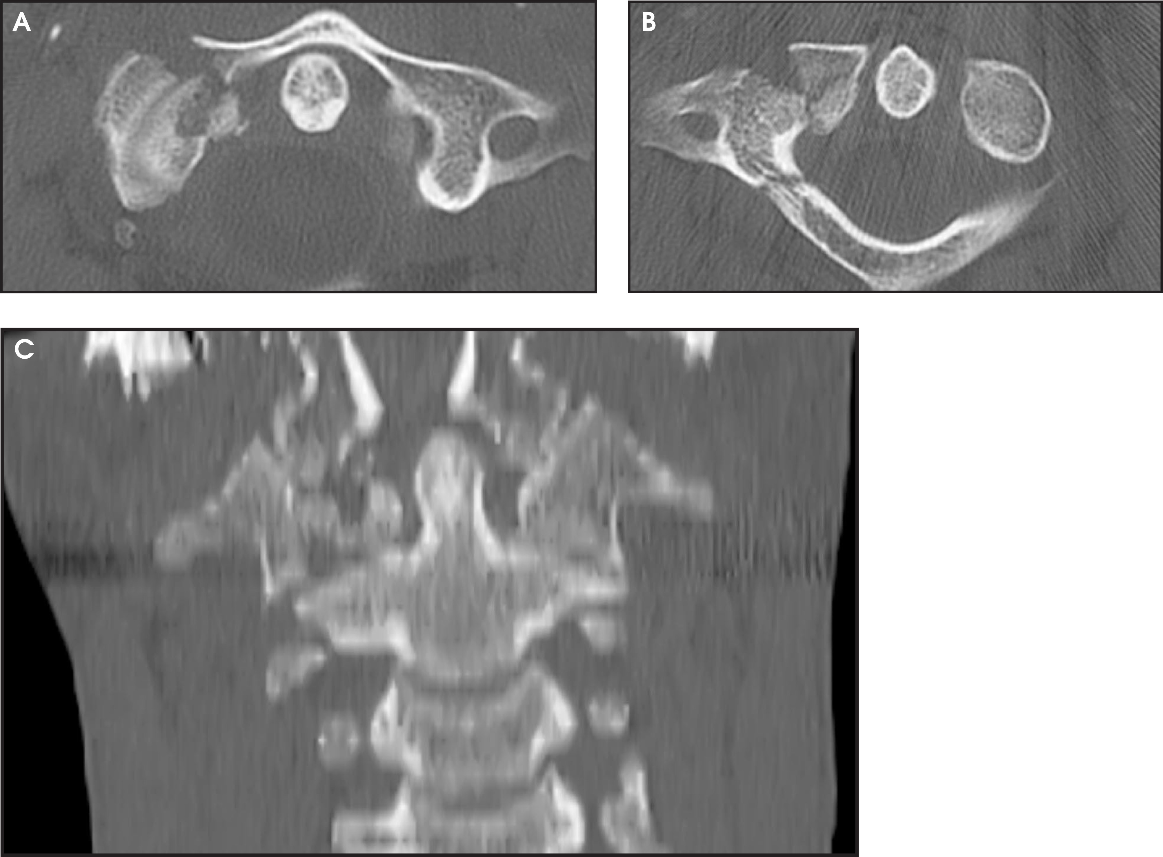
Most of the CT images presented in this article were obtained on a General Electric LightSpeed QX/i CT scanner (GE Medical Systems, Milwaukee, WI) that has a 4-channel detector capable of making 4 simultaneous source axial images 1.25 to 5 mm thick. At The University of Texas, primary diagnostic images are scanned in the 4 × 1.25 mm mode, and 2.5 mm thick axial images using the bone algorithm are created. Images made in the HS mode (beam pitch 1.5) are of excellent quality, but many of the images presented in this article were made using the HQ mode (beam pitch 0.75). Sagittal and coronal reformatted images have been made using various techniques, with modifications made based on additional experience with multislice scanning. Our department’s current technique, which produces the best reformatted images, involves creating a set of 1.25-mm axial images spaced every 1.0 mm using the standard algorithm--the secondary raw data--which is made from the same raw data that is used to make our 2.5-mm primary diagnostic images. The secondary raw data is reformatted into 0.3- to 0.6-mm sagittal and coronal sections spaced every 2 to 3 mm. A less resource-intensive technique that also produces excellent reformatted images is to use 1.25-mm images spaced every 1.25 mm made with the bone algorithm. These are reformatted into 2-mm sagittal and coronal images spaced every 2 to 3 mm. The thicker reformatted images reduce image noise, which is a problem when bone algorithm is used. The least aesthetically pleasing images in this article were made using an older technique wherein the 2.5-mm primary diagnostic images were reformatted into 0.3- to 0.6-mm sagittal and coronal sections spaced every 3 to 4 mm. Images made with this older technique have less detail, more image noise, and suffer from noticeable stairstep artifact. Nevertheless, the images are adequate for diagnosis and are of sufficient educational value to merit their inclusion in this pictorial essay.
After studying these cases of C0–C1 upper cervical spine injury, there are several important facts to remember: 1) fractures of the C0–C1 region are often, but not always, detectable radiographically; 2) prevertebral soft-tissue swelling is helpful when present, but the absence of swelling does not exclude an upper cervical spine injury; 3) because radiographs are not completely sensitive for detection of potential unstable injuries in the C0–C1 region, screening high-risk trauma patients for injury using CT is a logical approach8; and 4) because C0–C1 injuries may be difficult to detect or evaluate completely using axial CT alone, high-quality radiographs or high-quality sagittal and coronal reformatted images should be part of the routine evaluation of the C0–C1 region. AR
References
- Clark C. The Cervical Spine. 1998.
- Anderson P, Clark C. The Cervical Spine. 1998:387-399.
- Deliganis A, Baxter A, Hanson J. Radiologic spectrum of craniocervical distraction injuries. RadioGraphics. 2000:S237-250.
- Harris J, Carson G, Wagner L. Radiologic diagnosis of traumatic occipitovertebral dissociation: 1. Normal occipitovertebral relationships on lateral radiographs of supine subjects. AJR Am J Roentgenol. 1994;162:881-886.
- Kurz L, Clark C. The Cervical Spine. 1998:409-413.
- Vaughan T, West O. Isolated vertical fracture through the anterior atlas arch: A previously unreported fracture. Emerg Radiol.. 1998;5:259-262.
- Spence K, Decker S, Sell K. Bursting atlantal fracture associated with rupture of the transverse ligament. J Bone Joint Surg Am.. 1970;52:543-549.
- Blackmore C, Ramsey S, Mann F, Deyo R. Cervical spine screening with CT in trauma patients: A cost-effectiveness analysis. Radiology. 1999;212:117-125.
Citation
. Imaging of upper cervical spine injuries—Part I: C0–C1. Applied Radiology. 2002;31(2):23-32. doi:10.37549/AR1076.