MRI of temporomandibular joint disorders
Applied Radiology — Vol. 37 , Issue 9 , pp. 17 -25
DOI: 10.37549/AR1649
Published: September 1, 2008
Categories
Approximately 10 million individuals in the United States are affected by temporomandibular joint (TMJ) abnormalities (National Institutes of Health data, National Institute of Dental and Craniofacial Research).1 The highest prevalence of temporomandibular disorders (TMD) is in women aged 20 to 40 years, with women representing 80% of patients being treated for TMD.2,3 Magnetic resonance imaging (MRI) plays an important role in the evaluation of TMD, as it allows for a noninvasive depiction of the joint that is not otherwise available. Moreover, clinical diagnosis of TMJ abnormalities can be challenging, particularly given the psychosocial factors that can be involved in pain disorders. The diagnostic accuracy of the clinical examination is variable, ranging from 54% to 90%.4
TMJ anatomy and function
Major components of the TMJ include the mandibular condyle, the articular disc, the glenoid fossa, and the articular eminence of the temporal bone (Figure 1). Unlike most joints, the articulating surfaces are fibrous and not cartilaginous. The fibrocartilaginous articular discis biconcave, dividing the joint space into superior and inferior compartments; this relationship is well seen in the presence of joint effusion (Figure 2). The anterior and posterior portions of the articular disc, which are thickened by the morphology of the disk annulus, are designated the anterior band and the posterior band, respectively, with a thinner intermediate zone in between. The disc is attached to the temporal bone and condyle posteriorly by elastic and loose connective tissue; this tissue is also known as theretrodiscal soft tissue or thebilaminar zone. The lateral pterygoid muscle, the only muscle of mastication serving to open the jaw, inserts on the mandibular condyle inferior to the articular surface but can partially insert on the joint capsule and disc as well.
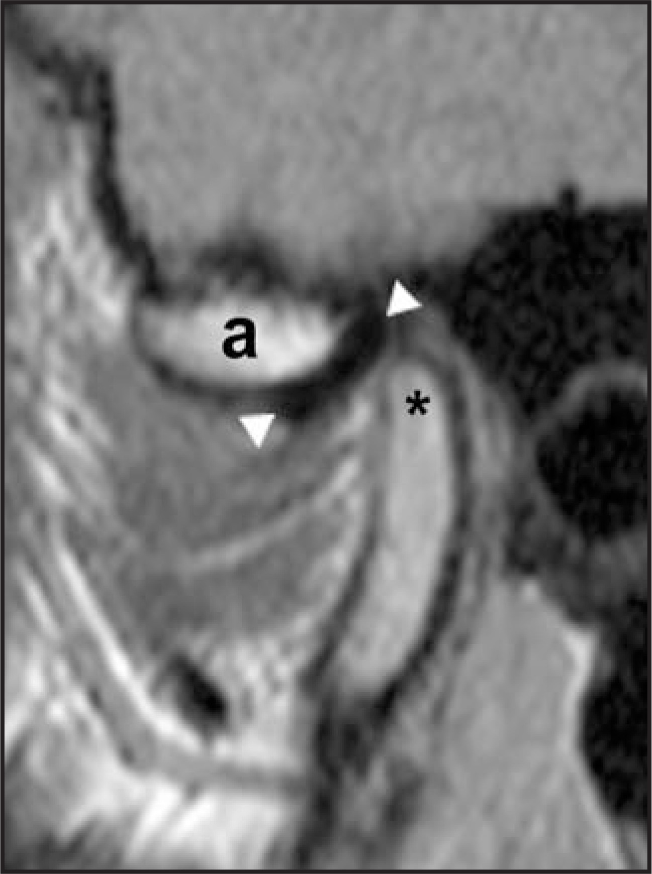
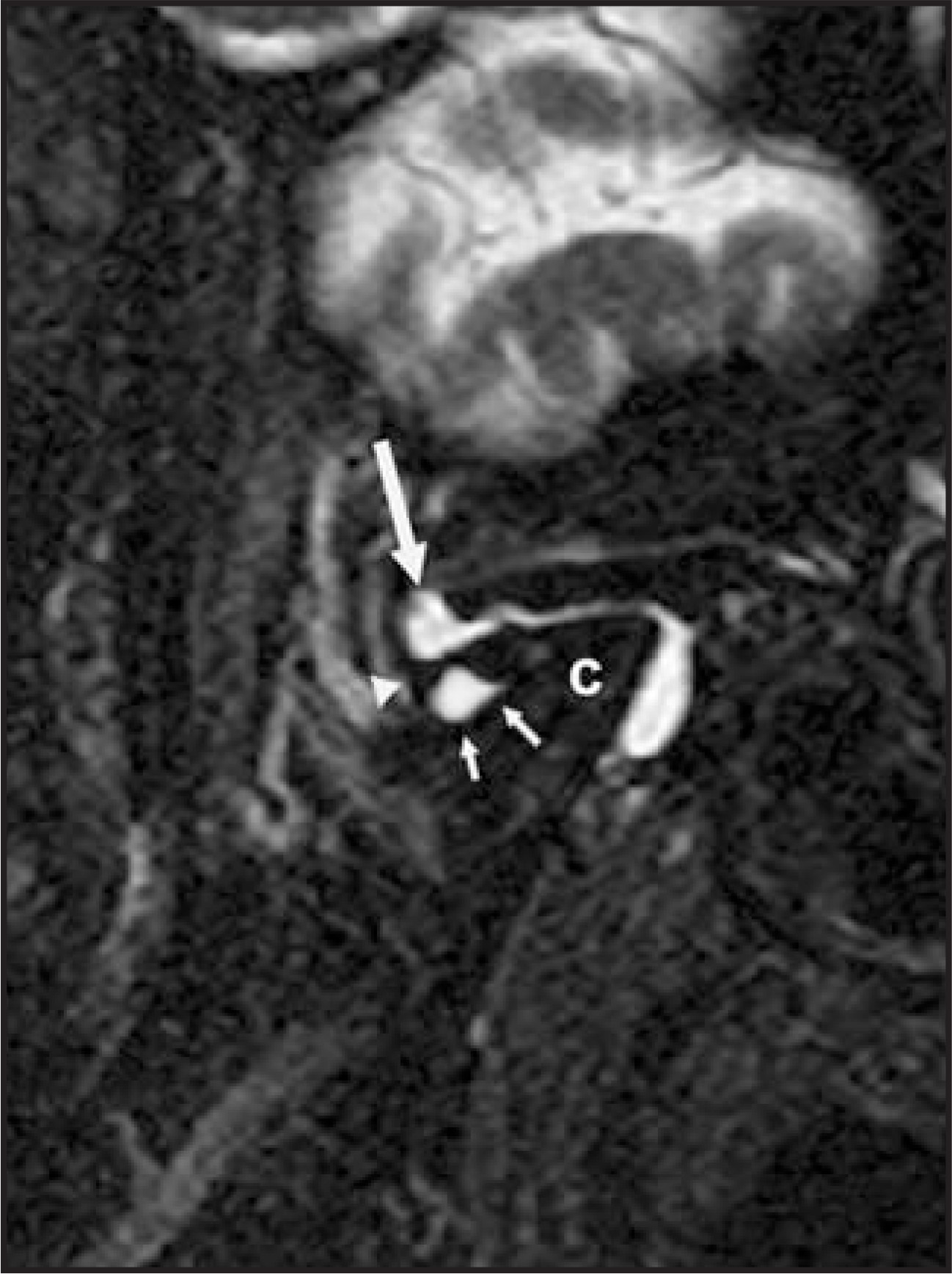
The presence of what are essentially 2 separate joints (superior and inferior) allows for a high range of motion relative to the size of the joint complex. Translational and rotational components of condylar motion are present, with translation occurring more notably at the upper jointspace, and a more rotational component of motion occurring at the inferior joint space. During the opening of the mouth, motion commences as rotation, followed by translation; up to 15 to 20 mm of opening (interincisor distance) can be achieved with simple rotation at the joint. During translation, the disc and condyle move under the articular eminence; the intermediate zone of the disc remains interposed between the articular eminence and mandibular condyle.
TMD
Major classes of TMD include internal derangement, osteoarthrosis, and myofascial syndromes, the first 2 of which can be seen with MRI. Internal derangement refers to a mechanical process that prevents smooth joint function. Osteoarthrosis is a noninflammatory joint disease that results in osseous remodeling and degeneration of articular surfaces. In the TMJ, it is closely related to the presence of internal derangement.5
In TMD, internal derangement typically results from disc displacement. The displacement is often anterior, although a medial or lateral component is also often present as well; this occurs when the compressive forces on the condyle can no longer be resisted by the disc annulus.6 Early in the development of TMJ degeneration, anterior disc displacement with reduction is present. On opening, there is reduction of disc displacement, with displacement again occurring upon closing of the jaw as the condyle translates posteriorly. During the process of disc displacement and reduction, clicks can be present. However, the significance of minor anterior disc displacements with reduction as identified on imaging is controversial, as a high prevalence of displacement (up to 33%) is seen in asymptomatic volunteers.7It is possible that these volunteers may have had earlier stage internal derangement; no studies at this point have followed asymptomatic patients withdisc displacement as documented by MRI.
It is theorized that over time, increased laxity of the retrodiscal soft tissues results in a progression of disease with eventual development of worsened anterior disc displacement without reduction (Figure 3). In anterior disc displacement without reduction, the disc remains displaced. Early in the disease process, there may be limitation of motion, with deviation of the jaw toward the affected joint, or even a closed lock. However, as there is progressive stretching of retrodiscal tissues, the range of motion increases. Later on, disc deformity canoccur and frank perforation of the posterior disc attachment can be seen.8
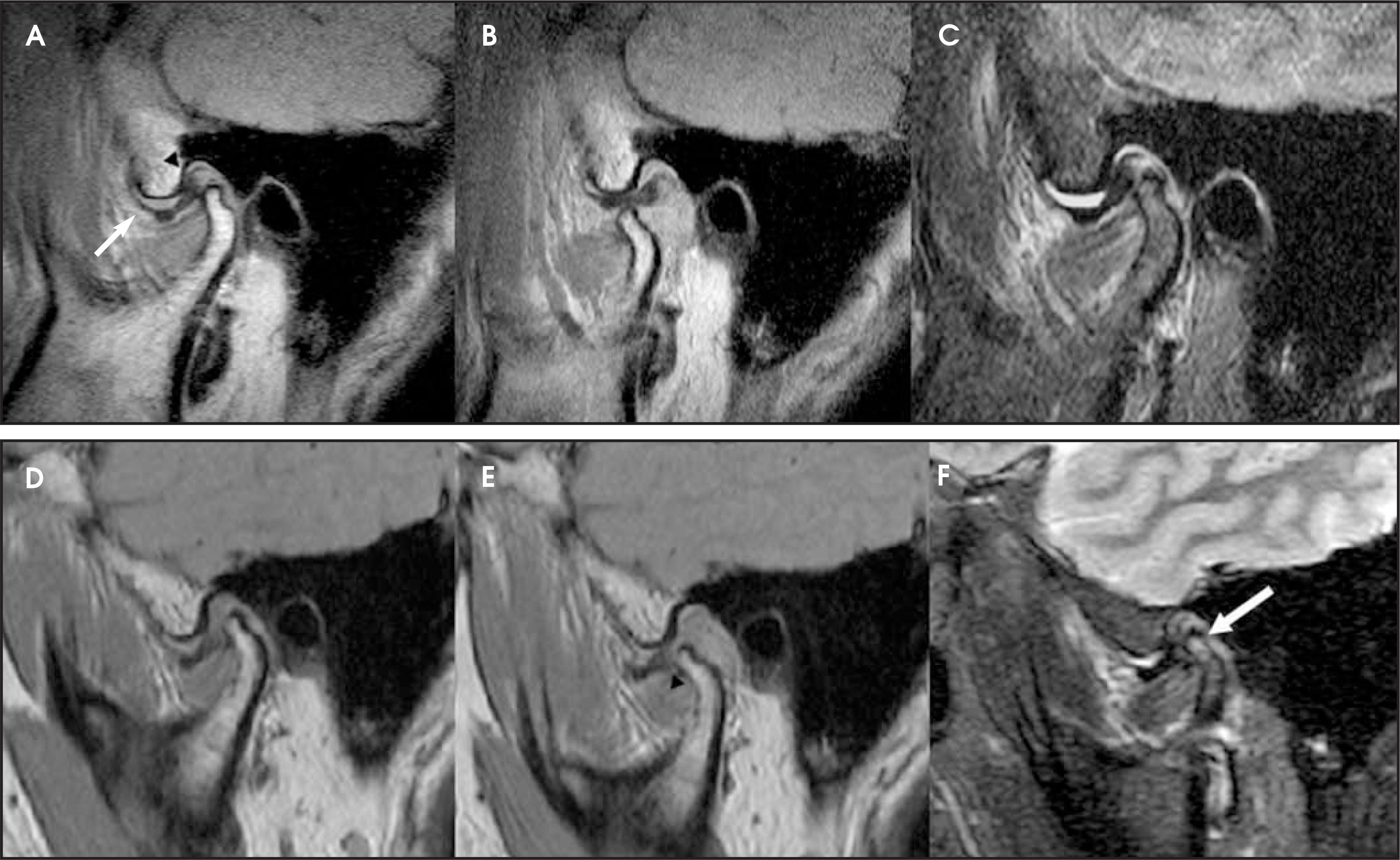
Uncommonly, an open lock can occur when the mandibular condyle is unable to translate back into the glenoid fossa, whether duetoposteriorly displaced disc material or due to the articular eminence (Figure 4). Nonsurgical treatment options in the setting of TMD include rehabilitative exercise programs, arthrocentesis and lavage, and arthroplasty; surgical options include disc repositioning, discectomy, and recontouring of the articular eminence. The role of surgical versus nonsurgical treatment is complicated by the fact that TMD symptoms decrease with age and are often self-limiting.9
Imaging considerations
Computed tomography (CT) is helpful in assessing the osseous structures of the temporomandibular joint. The evaluation of erosive change, trauma, postsurgical change, and the remainder of temporal bone are best assessed with CT. In contrast, MRI is useful in evaluating the soft tissues, particularly in its assessment of the articular disc. With MRI, near-cinematic dynamic imaging studies are also possible, and no ionizing radiation is needed, which may be of benefit given the number of young female patients affected by TMD. Because of its excellent anatomic depiction of the joint, in many scientific studies, MRI of the TMJ is considered the imaging gold standard. Parallel imaging technology allows for the rapid acquisition of TMJ imaging without the use of a dedicated surface loop coil; this can be advantageous when a source of head pain is elicited in a patient, allowing for rapid MR evaluation of both the TMJ and intracranial compartment.
At the authors’ institution, the TMJ MRI protocol makes use of both static and dynamic imaging, all performed in the same multichannel head coil (Table 1). Altogether, this protocol takes approximately 25 minutes. The authors use proton-density imaging for our sagittal oblique staticevaluation of the joint, as the disc is well seen as a hypointense biconcave structure between the condyle and articular eminence. It should be noted that while sagittal and coronal oblique images are oriented to the long and short axes of the condylar head as seen on axial imaging. Dynamic imaging is performed in straight sagittal orientation along the anticipated path of condylar motion.
Postcontrast imaging can be helpful in evaluating inflammatory arthritis by allowing the distinction of pannus formation from effusion. Some authors describe improved visualization of the disc and soft tissues with contrast-enhanced imaging. In a set of 50 TMJs studied on a 0.5T magnet, Takebayashi et al10found that visualization of the disc on T1-weighted imaging was improved in >50% of cases. Increased enhancement of the upper joint space has also been documented in cases of internal derangement; this enhancement may be caused by synovitis.11 However, the additive value of postcontrast imaging in standard TMD evaluation has not been fully established at higher field strengths relative to proton-density imaging. At the authors’ institution, intravenous contrast is not routinely used unless there is suspicion of inflammatoryarthritis or neoplasm.
Findings in TMJ degeneration
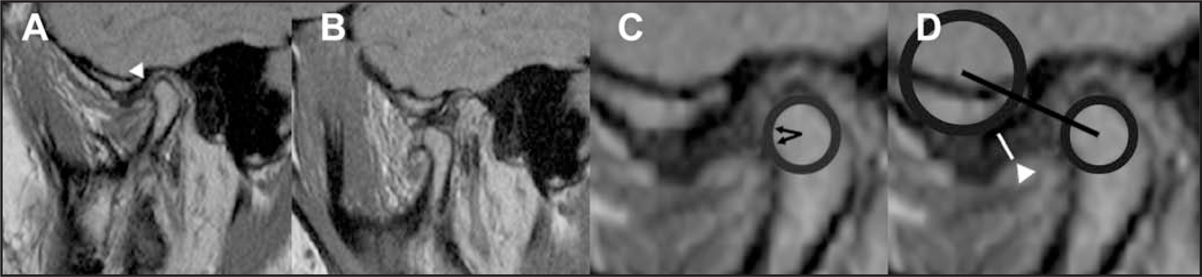
Disc displacement—A critical point of analysis in the evaluation of TMJ MRIis the position of the disc, as disc displacement is present in approximately 80% of patients with TMD who undergo MRI (Figure 5).12On normal sagittal oblique closed-mouth images, a commonly cited standard for normal disc position on MRI is visualization of the posterior margin of the posterior band at an 11:00 position or more posterior clockface position above the mandibular condyle.13 This margin will be seen anterior to this in the setting of anterior displacement; if present, the degree of displacement is identified on open-mouth imaging. Given some degree of subjectivity of the clock-face interpretation with the size of the condyle and the possibly difficult visualization of the margin of the posterior band (particularly in the degenerated disc), some advocate evaluating the position of the intermediate zone, looking for its interposition between the articular eminence and mandibular condyle.14
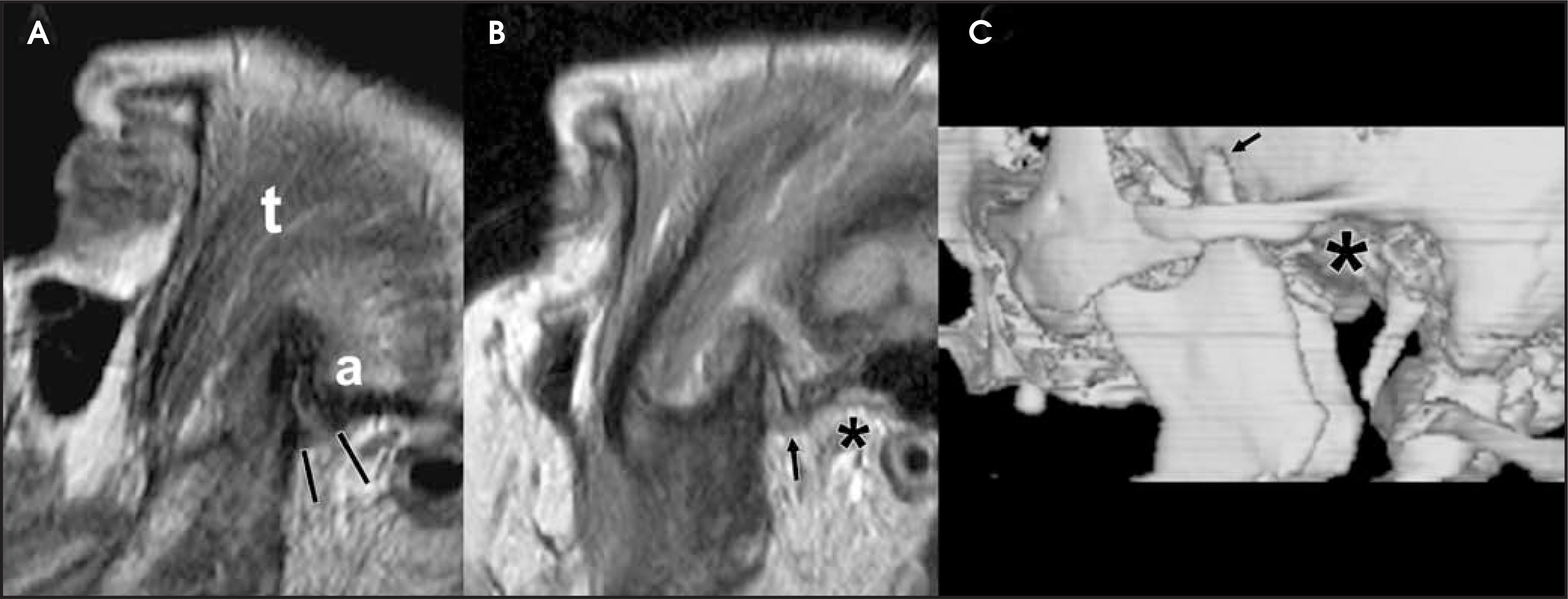
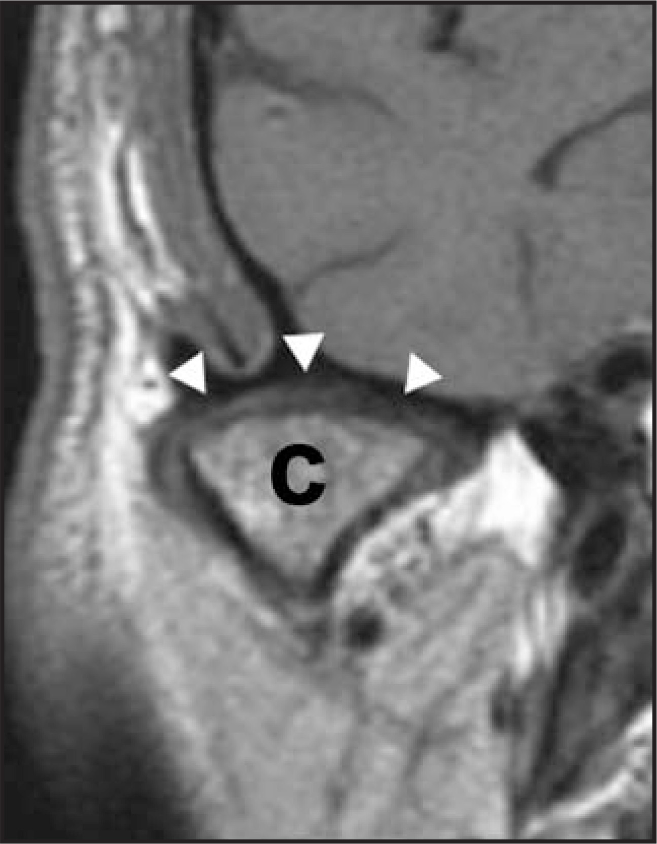
Mediolateral disc displacement is best identified on coronal oblique imaging. Typically, disc material is seen as symmetric crescentic hypointense material seen above the condylar head and on the image slice just anterior to the condyle (Figure 6). Mediolateral disc displacement will be seen with a disproportionate amount of disc material to either side of the condyle (Figure 7). Schmitter et al15have reported that up to 20% of asymptomatic individuals are found to have medial disc displacement.15 In some cases, a “stuck disc” is identified, typically due to fibrous adhesions that prevent any disc motion. This finding is well delineated on static and closed-mouth imaging (Figure 8).
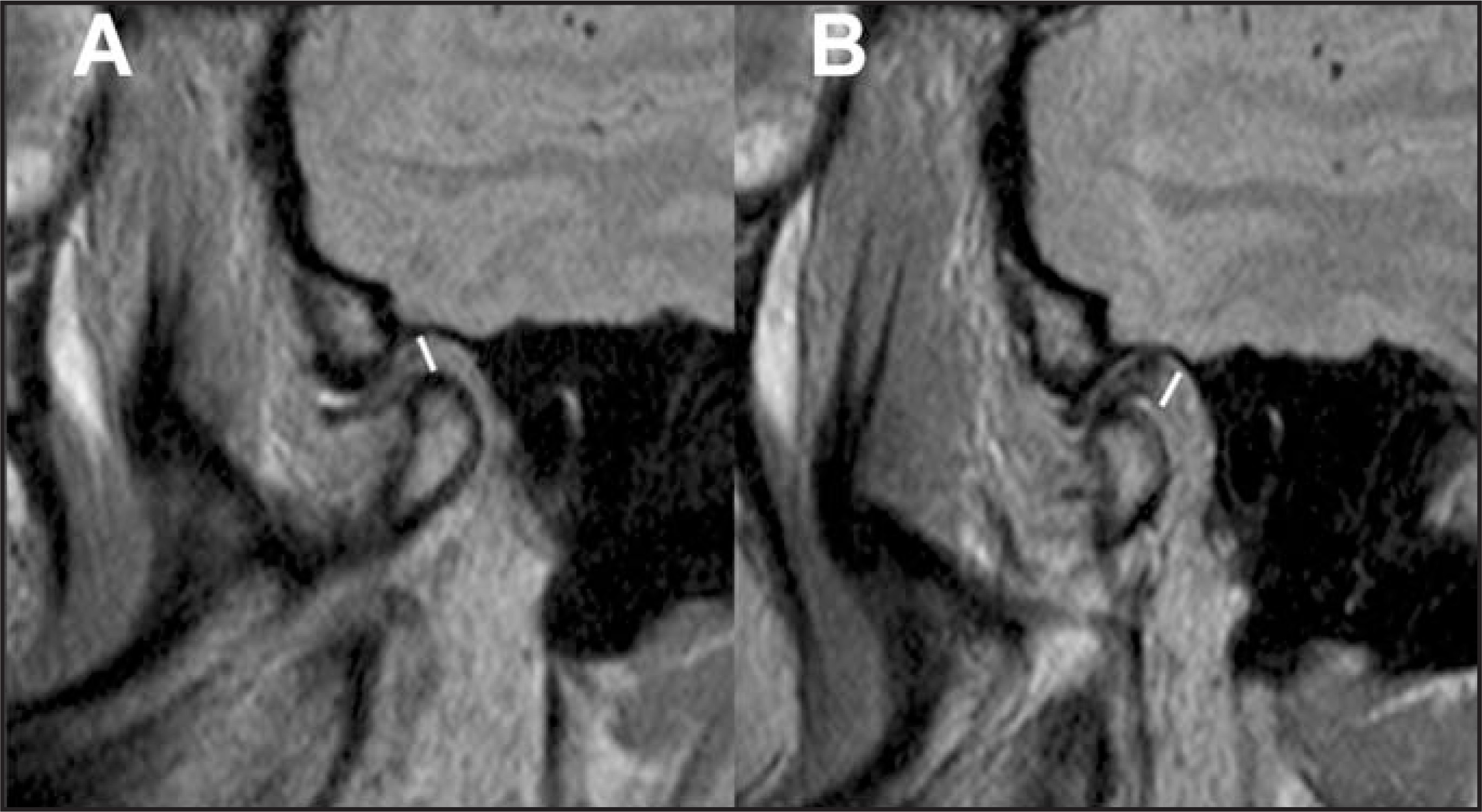
Disc deformity and perforation—As degeneration of the joint ensues, the disc will assume a deformed appearance, losing its biconcave appearance, and shortening in the anteroposterior dimension (Figure 9). An increase in signal can also be seen on proton-density imaging. If the disc is difficult to visualize on proton-density imaging, it is likely that significant disc degeneration has occurred. Gross deformity raises the possibility that simple arthrocentesis, lavage, and repositioning procedures may not be as successful, and that more aggressive surgery may be needed. Disc perforations may hold similar clinical significance and also can be associated with chondromalacia.16
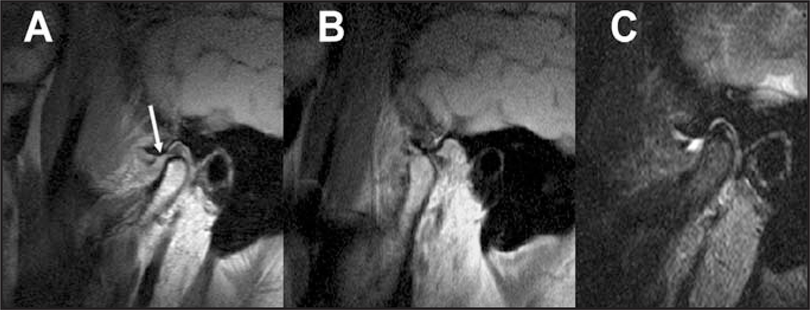
Joint effusion and marrow edema—These are well seen on sagittal oblique short tau inversion recovery (STIR) images (Figure 10);separate components can be seen at both superior and inferior joint spaces. Marrow edema is also well depicted on STIR imaging. It has been theorized that bone marrow signal abnormalities on MRI may simply reflect edema or osteonecrosis, separate from osteoarthrosis.17Sano et al18reported that joints with bone marrow signal alterations were more painful when compared with joints with normal bone marrow signal.
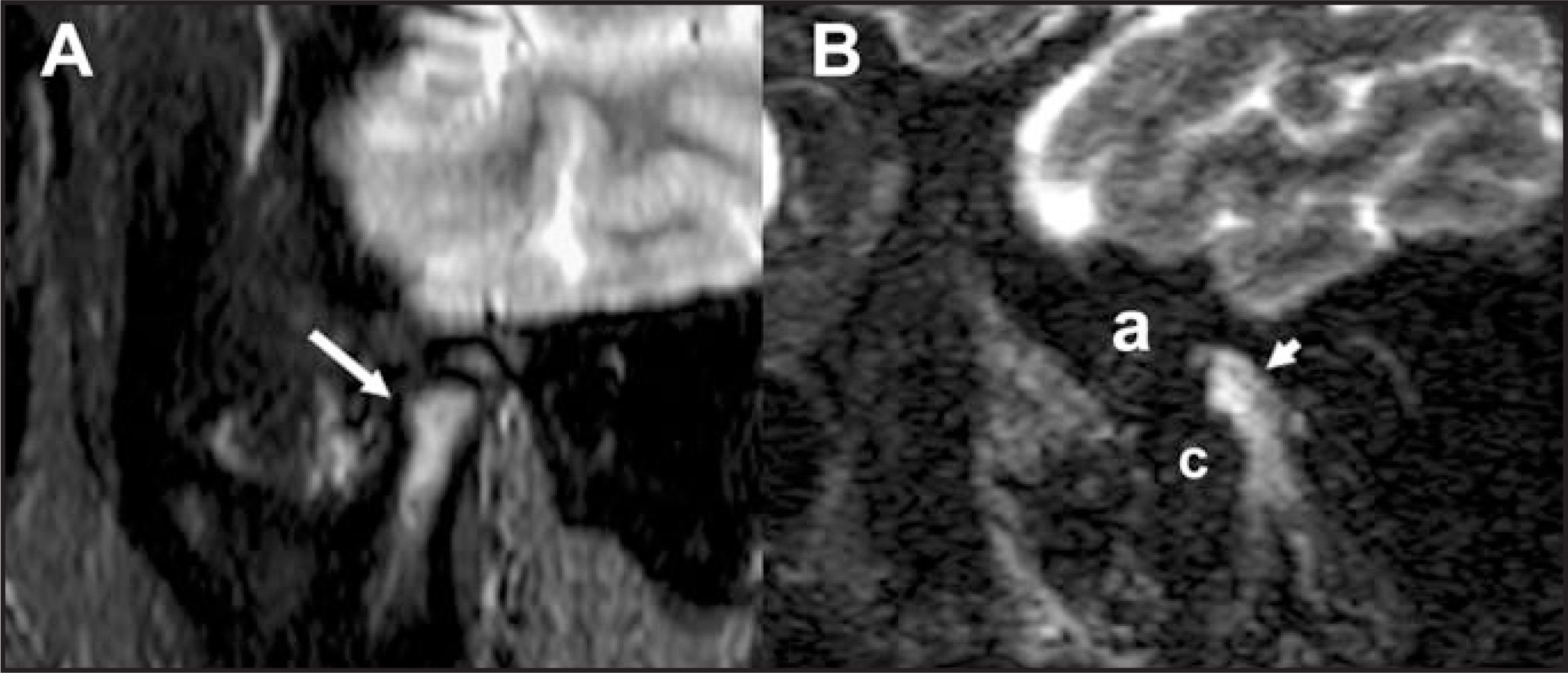
Osteoarthrosis—Osteophyte formation along the mandibular condyle and articular eminence can be seen in the setting of osteoarthrosis(Figure 11). Additional changes include a decrease in marrow signal on proton-density and STIR imaging compatible with sclerosis, as well as subchondral cyst formation. Pronounced osteoarthrosis can be seen in the posttraumatic setting. Advanced osteoarthrosis is often seen inthe elderly and is frequently asymptomatic. This may reflect the end-stage of TMJ degeneration, in which range of motion is preserved as the degenerated disc is anteriorly displaced without reduction.
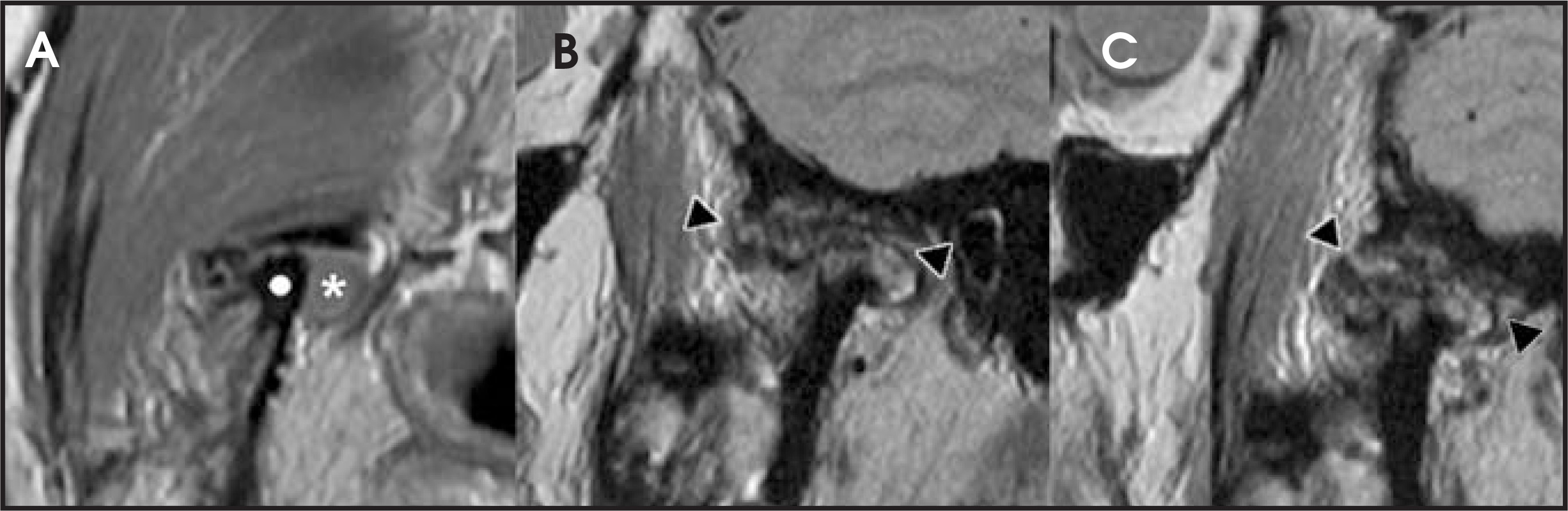
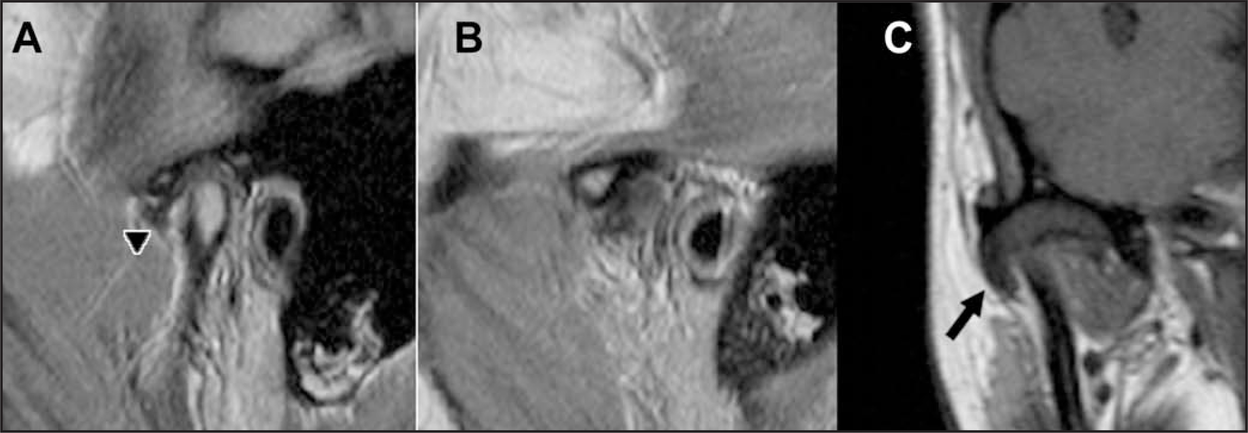
Lateral pterygoid muscle (LPM) abnormalities—Recent work has noted the importance of the lateral pterygoid muscle.19It is known that the inferior belly of the lateral pterygoid muscle becomes hyperactive in the setting of TMD. Hypertrophy, atrophy, and fibrosis of the LPM have been noted in patients with TMD and clinical symptoms of pain and limited range of motion. Sometimes a thickened attachment can simulate anterior extension of the articular disc (Figure 12).
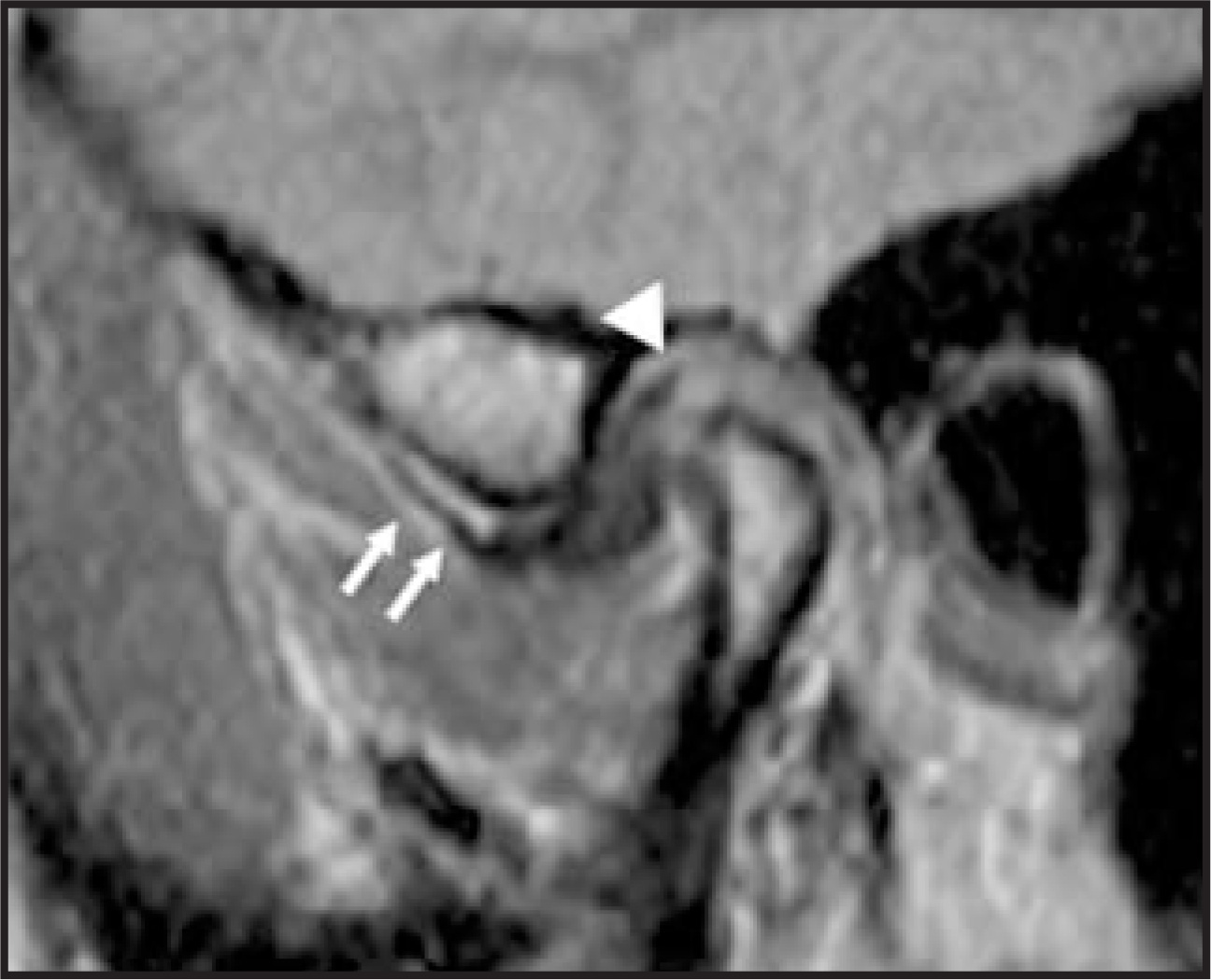
Retrodiscal abnormalities—Sano et al20described increased retrodiscal soft tissue T2 signal in painful joints, likely a function of hyperemia and perivascular inflammation (Figure 10). Others have described increased contrast enhancement in painful joints.21More chronic pathology is likely represented by fibrotic changes, with a decrease in T2 signal, which can also produce a pseudodisc sign, with thickening of the posterior meniscal attachment (Figure 12). Tomas et al22also described rupture of the retrodiscal soft tissues as a sign of degeneration. While it has been suggested that fibrosis may account for eventual decreases in pain in the evolution of TMJ, this opinion has not been substantiated in the literature.23
As the decision to treat patients is made primarily on the basis of patient symptoms—most notably the range of motion and presenceof pain24—it may be prudent to focus on the imaging findings that are most linked to these complaints. In a recent study by Emshoff etal,25the MR findings most associated with TMJ pain were disc displacement without reduction and the presence of bone marrow edema.
Dynamic imaging
Current MR technology allows dynamic near-cinematic imaging of the disc. We have found that these studies have provided information additive to routine static imaging in some cases.26Advantages include a near real-time assessment of the true range of motion, shortduration of acquisition (35 seconds), and the ability to acquire imaging in a head coil without a dedicated jaw-opening appliance, which allows it to be included in most imaging protocols. Despite a reduced matrix, the disc and its relative position are well assessed (Figure 13). A side benefit of the half-Fourier acquisition single-shot turbo spino-echo (HASTE) imaging protocol is generally reduced susceptibility artifact, which can improve diagnostic yield in the setting of extensive dental hardware.
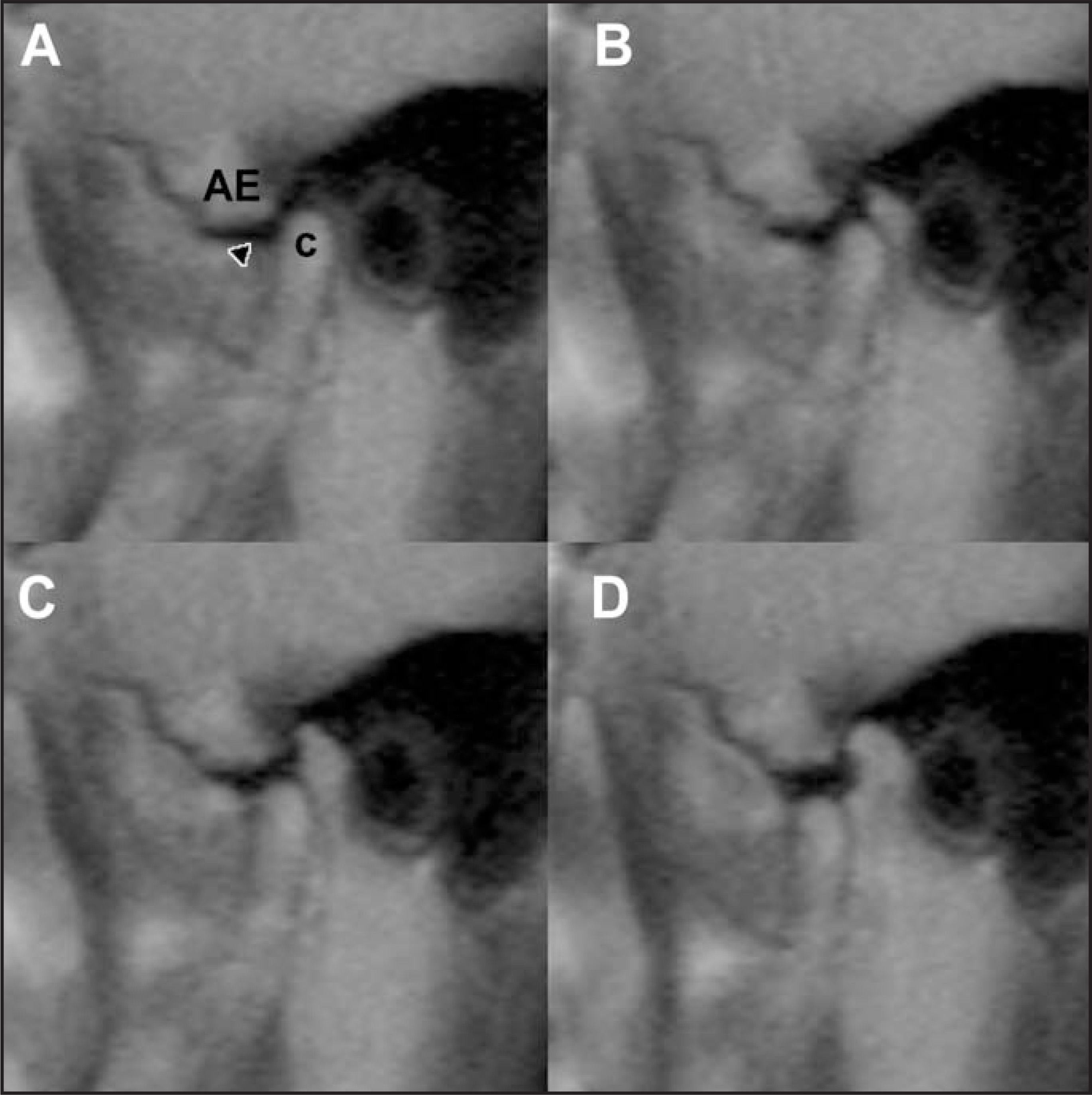
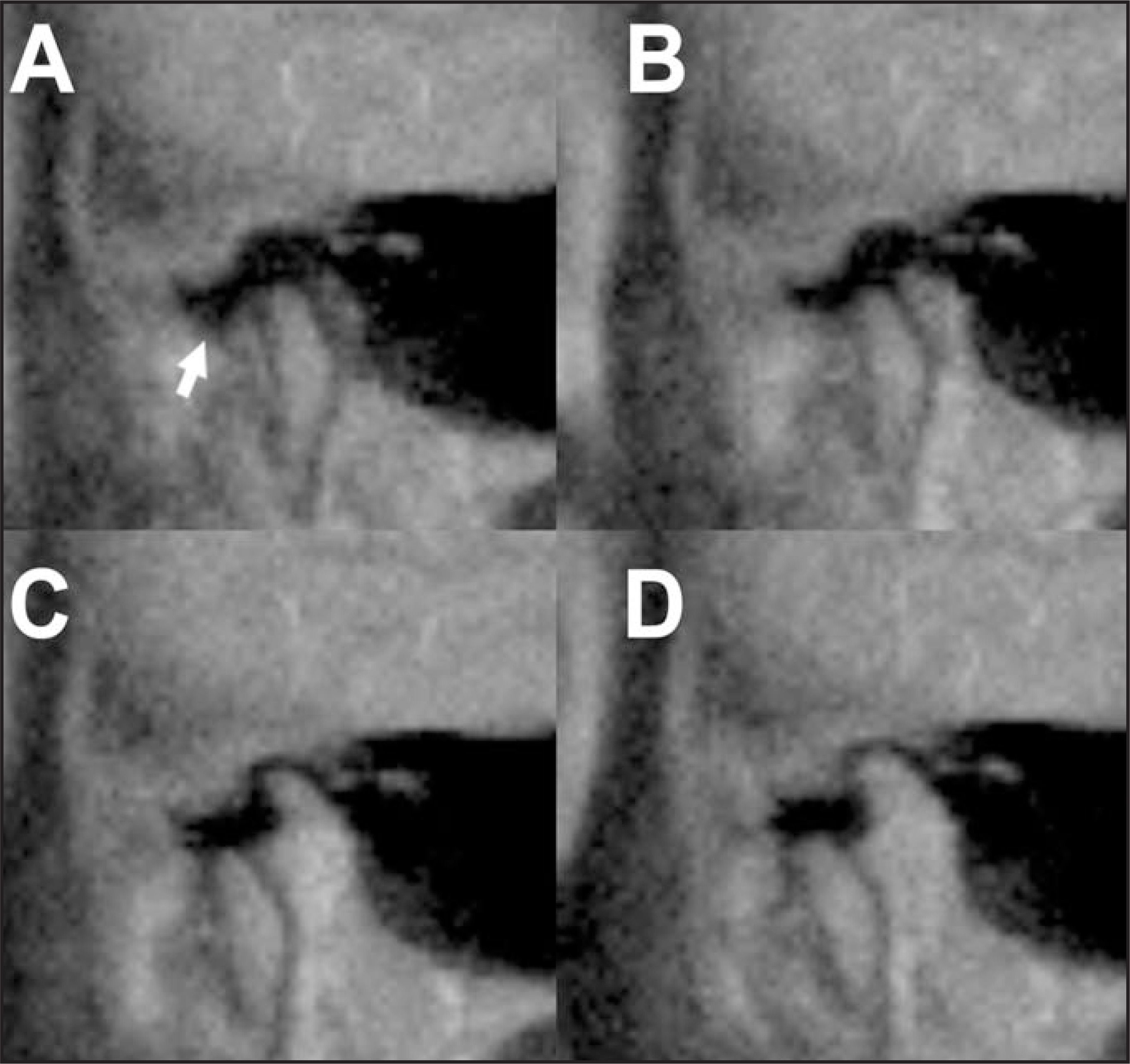
As imaging is performed in a direct sagittal plane, and not a sagittal oblique plane, the position of the disc is assessed by observing the intermediate zone. One expects its position to be interposed between the radial centers of the articular eminence and the mandibular condyle. In the setting of anterior disc displacement, the authors have seen dynamic imaging findings of visualization of reduction of disc material and of bulging of the anterior margin of the anterior band (Figure 14), even in cases where routine static imaging is normal. On dynamic imaging, a normal range of motion is present when the condyle has translated to the apex of the articular eminence. Normal individuals will often be able to translate beyond this point on a transient basis.
Conclusion
MRI examinations of the TMJ are part of the current standard of care in the evaluation of TMD, providing the clinician anatomic information that can guide treatment decisions. This article has reviewed some of the key findings and imaging appearances of the degenerated TMJ. Further research will continue to enhance our understanding of the potential contributions of contrast-enhanced studies and dynamic imaging.
References
- TMJ (Temporomandibular Joint and Muscle Disorders). 2007.
- Kuttila M, Niemi P, Kuttila S. TMD treatment need in relation to age, gender, stress, and diagnostic subgroup. J Orofac Pain. 1998;12(1):67-74.
- LeResche L. Epidemiology of temporomandibular disorders: implications for the investigation of etiologic factors. Crit Rev Oral Biol Med. 1997;8:291-305.
- Usümez S, Oz F, Guray E. Comparison of clinical and magnetic resonance imaging diagnoses in patients with TMD history. J Oral Rehab. 2004;31:52-56.
- Bertram S, Rudisch A, Innerhofer K. Diagnosing TMJ internal derangement and osteoarthritis with magnetic resonance imaging. J Am Dent Assoc. 2001;132:753-761.
- Osborn J. The disc of the human temporomandibular joint: Design, function and failure. J Oral Rehabil. 1985;12:279-293.
- Katzberg R, Westesson P, Tallents R, Drake C. Anatomic disorders of the temporomandibular joint disc in asymptomatic subjects. J Oral Maxillofac Surg. 1996;54:147-153.
- Styles C, Whyte A. MRI in the assessment of internal derangement and pain within the temporomandibular joint: A pictorial essay. Br J Oral Maxillofac Surg. 2002;40:220-228.
- Rasmussen O. Description of population and progress of symptoms in a longitudinal study of temporomandibular arthropathy. Scand J Dent Res. 1981;89:196-203.
- Takebayashi S, Takama T, Okada S. MRI of the TMJ disc with intravenous administration of gadopentetate dimeglumine. J Comput Assist Tomogr. 1997;21:209-215.
- Ogasawara T, Kitagawa Y, Ogawa T. Inflammatory change in the upper joint space in temporomandibular joint with internal derangement on gadolinium-enhanced MR imaging. Int J Oral Maxillofac Surg. 2002;31(3):252-256.
- Tasaki M, Westesson P, Isberg A. Classification and prevalence of temporomandibular joint disk displacement in patients and symptom-free volunteers. Am J Orthod Dentofacial Orthop. 1996;109:249-262.
- Rammelsberg P, Pospiech P, Jäger L. Variability of disk position in asymptomatic volunteers and patients with internal derangements of the TMJ. Oral Surg Oral Med Oral Pathol Oral Radiol Endod. 1997;83:393-399.
- Helms C, Kaplan P. Diagnostic imaging of the temporomandibular joint: Recommendations for use of the various techniques. AJR Am J Roentgenol. 1990;154:319-322.
- Schmitter M, Kress B, Ludwig C. Temporomandibular joint disk position assessed at coronal MR imaging in asymptomatic volunteers. Radiology. 2005;236:559-564.
- Quinn J. Arthroscopic management of temporomandibular joint disc perforations and associated advanced chondromalacia by discoplasty and abrasion arthroplasty: Preliminary results. J Oral Maxillofac Surg. 1994;52.
- Larheim T, Westesson P, Hicks D. Osteonecrosis of the temporomandibular joint: Correlation of magnetic resonance imaging and histology. J Oral Maxillofac Surg. 1999;57.
- Sano T, Westesson P, Larheim T, Takagi R. The association of temporomandibular joint pain with abnormal bone marrow in the mandibular condyle. J Oral Maxillofac Surg. 2000;58.
- Taskaya-Yilmaz N, Ceylan G, Incesu L, Muglali M. A possible etiology of the internal derangement of the temporomandibular joint based on the MRI observations of the lateral pterygoid muscle. Surg Radiol Anat. 2005;27(1):19-24.
- Sano T, Westesson P. Magnetic resonance imaging of the temporomandibular joint. Increased T2 signal in the retrodiskal tissue of painful joints. Oral Surg Oral Med Oral Pathol Oral Radiol Endod. 1995;79:511-516.
- Suenaga S, Abeyama K, Noikura T. Gadolinium-enhanced MR imaging of temporomandibular disorders: Improved lesion detection of the posterior disk attachment on T1-weighted imagesobtained with fat suppression. AJR Am J Roentgenol. 1998;171:511-517.
- Tomas X, Pomes J, Berenguer J. MR imaging of temporomandibular joint dysfunction: A pictorial review. RadioGraphics. 2006;26:765-781.
- Westesson P, Paesani D. MR imaging of the TMJ. Decreased signal from the retrodiskal tissue. Oral Surg Oral Med Oral Pathol. 1993;76:631-635.
- Widmark G. On surgical intervention in the temporomandibular joint. Swed Dent J Suppl. 1997;123:1-87.
- Emshoff R, Brandlmaier I, Gerhard S. Magnetic resonance imaging predictors of temporomandibular joint pain. J Am Dent Assoc. 2003;134:705-714.
- Wang E, Mulholland T, Pramanik B. Dynamic sagittal half-Fourier acquired single-shot turbo spin-echo MR imaging of the temporomandibular joint: Initial experience andcomparison with sagittal oblique proton-attenuation images. AJNR Am J Neuroradiol. 2007;28:1126-1132.
Citation
. MRI of temporomandibular joint disorders. Applied Radiology. 2008;37(9):17-25. doi:10.37549/AR1649.