Vertebral body reconstruction: Review and update on vertebroplasty and kyphoplasty
Applied Radiology — Vol. 37 , Issue 12 , pp. 10 -24
DOI: 10.37549/AR1668
Published: December 1, 2008
Categories
Vertebroplasty is an invasive spine procedure that involves the injection of bone cement under fluoroscopic or computed tomographic (CT)guidance into a vertebral body that has been damaged as a result of either an osteoporotic vertebral compression fracture or neoplastic infiltration. Kyphoplasty, a derivative of vertebroplasty, entails the temporary placement and subsequent inflation of balloon tamps within the vertebral body prior to cement deposition. Vertebroplasty was first performed in 1984, while kyphoplasty was first performed more than a decadelater in 1998.1-3Both procedures have quickly become established as efficacious treatments for patients experiencing back pain related to osteoporotic or pathologic vertebral compression fractures.4This article will not only review these procedures, but will also discuss the rationale forthe clinical utility of vertebral body augmentation or reconstruction, review the clinical experience with vertebroplasty and kyphoplasty, anddiscuss advances in the field of vertebral body reconstruction. Finally, this article will emphasize the active role of the radiologist in the management of patients who present with vertebrogenic back pain, both prior to and after their fractures have been treated.
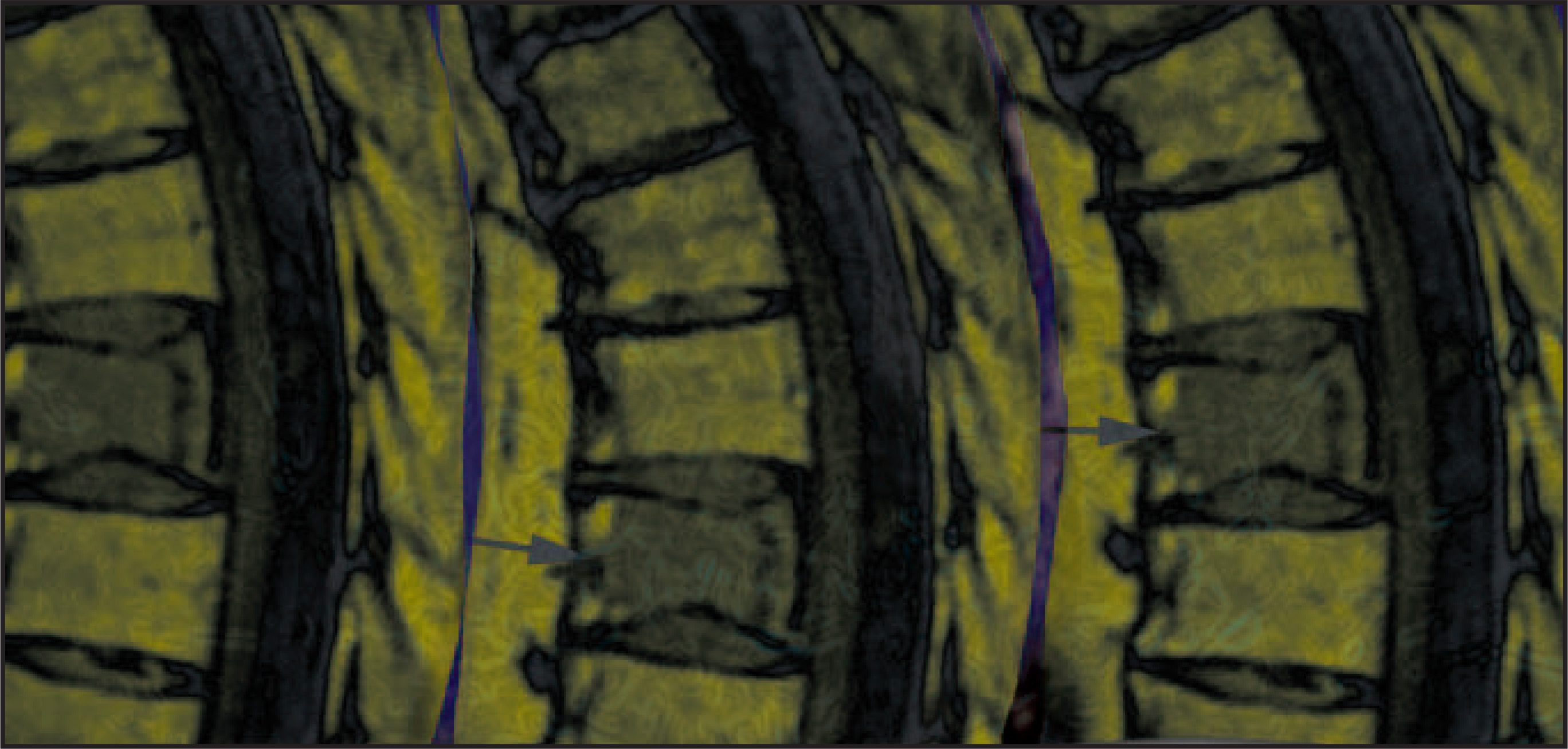
The vast majority of osteoporotic vertebral compression fractures occur within the thoracic and lumbar spine, particularly at the thoracolumbar junction. The fracture destabilizes the vertebral body, and macro- and micromotion at the fracture site causes pain. These fracturesimpact on the normal biomechanical alignment of the spine by causing the patient’s center of gravity to move forward and, thus, simultaneously creating a large anterior bending moment.5This alteration has significant adverse sequelae in that it places additional stress on the posterior paraspinal muscles and ligaments, predisposes to a loss of balance, and places additional stress on the anterior column such that adjacent and other vertebrae are at risk for compression. Longitudinal studies have shown that in the absence of any treatment the subsequentfracture risk in a patient with an osteoporotic vertebral fracture is 20% within the first year.6 A primary goal of vertebral augmentation, therefore, is to stabilize the fractured vertebra, reinforcing the anterior column and any endplate fractures, thereby alleviating pain. Another primary goal is to try to restore, as much as possible, spinal alignment and function to the prefracture status by restoring the vertebral bodyheight, reducing angulation at the fracture level, and minimizing kyphotic deformity. A secondary objective of these procedures is to prevent further vertebral body height loss. Not only is this associated with progressive kyphosis, but it is also associated with fractures at adjacent levels. The odds ratio for the development of new vertebral compression fractures increases to 20.6 when the patient’s actual height decreases >4 cm.7
With >700,000 osteoporotic vertebral compression fractures occurring each year in the United States alone, it must be kept in mind that not all of these patients require an invasive treatment.8In fact, some of these patients are not even aware that they have experienced a fracture. The potential candidates who could benefit from these procedures are those patients who are symptomatic and who have had an imaging study that shows a fracture that is responsible for their back pain symptoms.
Patient evaluation
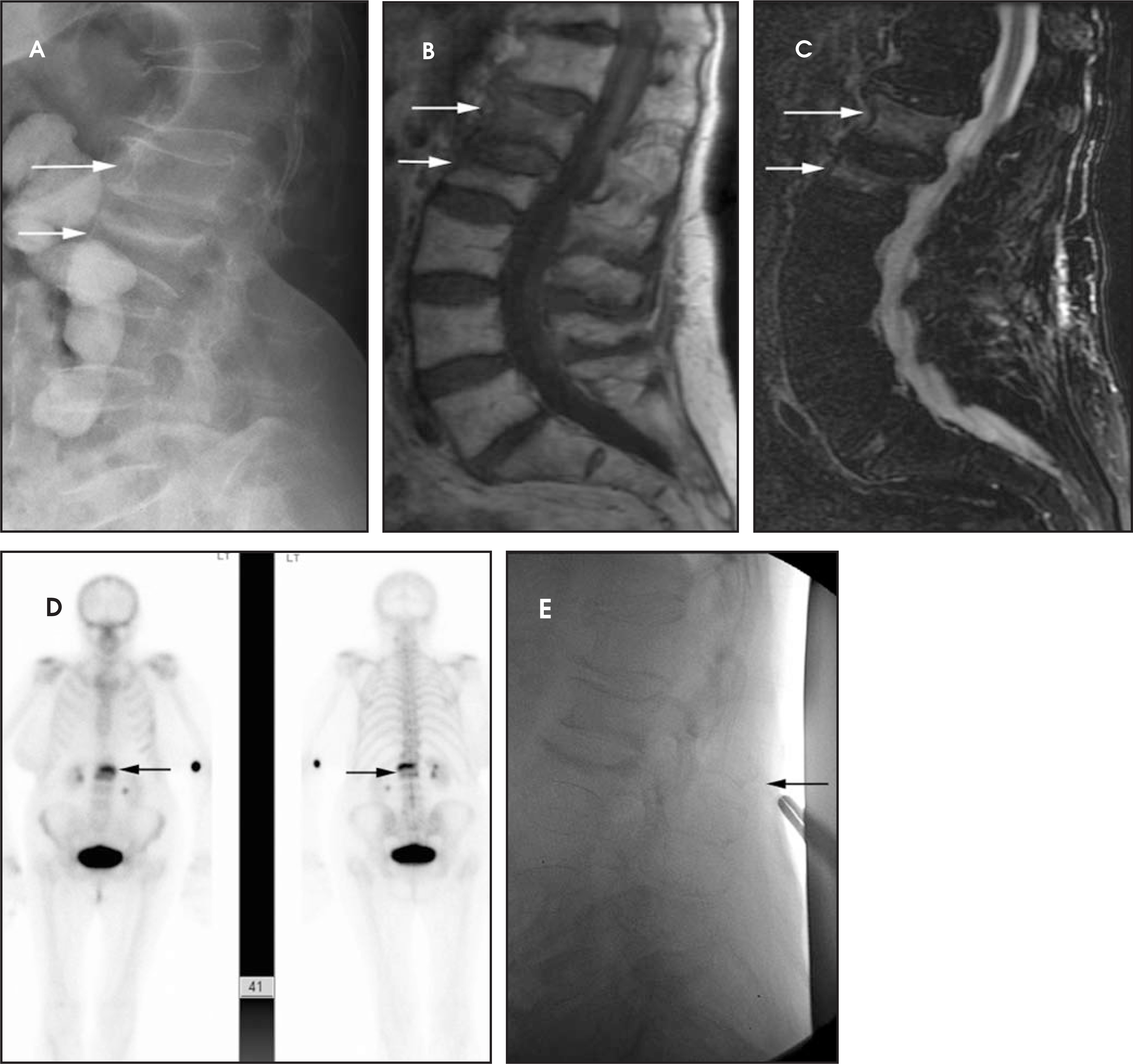
The role of imaging in the evaluation of a suspected vertebral compression fracture is extremely important in terms of patient selection.Many of these patients initially undergo radiographic evaluation. Plain radiographs can be helpful, as they may quickly identify an isolated fracture in a patient with acute severe back pain (Figure 1). Nevertheless, plain radiographs are insensitive and can miss acute fractures that have not yet resulted in height loss. Furthermore, in the absence of prior studies, it might be difficult to distinguish an acute fracture in the presence of multiple vertebral compression deformities in the spinal axis. Several studies have commented on the underreporting of vertebral compression fractures on radiographic studies.9
Radiologists should comment on the presence of vertebral compression deformities in their reports of patients who undergo chest or abdominal radio graphs. It is quite possible that the vertebral compression deformity, unbeknownst to the referring clinician, might be at least one cause of the patient’s clinical presentation. Alternatively, this might facilitate further screening for osteoporosis, in the form of bone density testing, leading to the initiation of osteoporosis treatment for the patient and the prevention of additional fractures.
Magnetic resonance imaging (MRI) is the most accurate examination that is available when evaluating patients with suspected vertebral compression fractures.10 Acute and subacute fractures can be readily identified because of the presence of marrow edema, which manifests as hypointense signal on T1-weighted images and hyperintense signal on T2-weighted and inversion recovery sequences (Figure 1). Vertebral body clefts, the result of avascular necrosis, are seen as fluid and/or air-containing foci located adjacent to a compressed vertebral endplate. Additionally, MRI can assess for spinal canal compromise by displaced fracture fragments and is capable of identifying other potential pain sources such as disc herniations or facet pathology. In many instances, MRI can also be used to differentiate between osteoporotic and pathologic vertebral compression fractures.
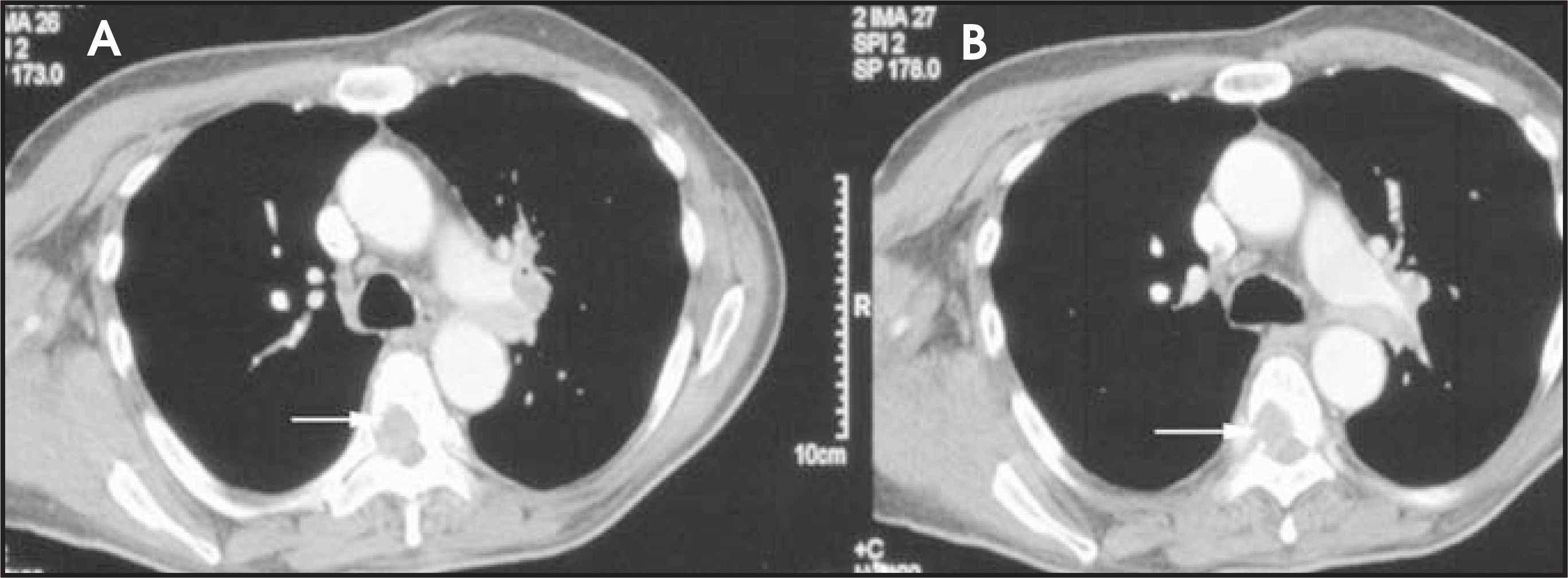
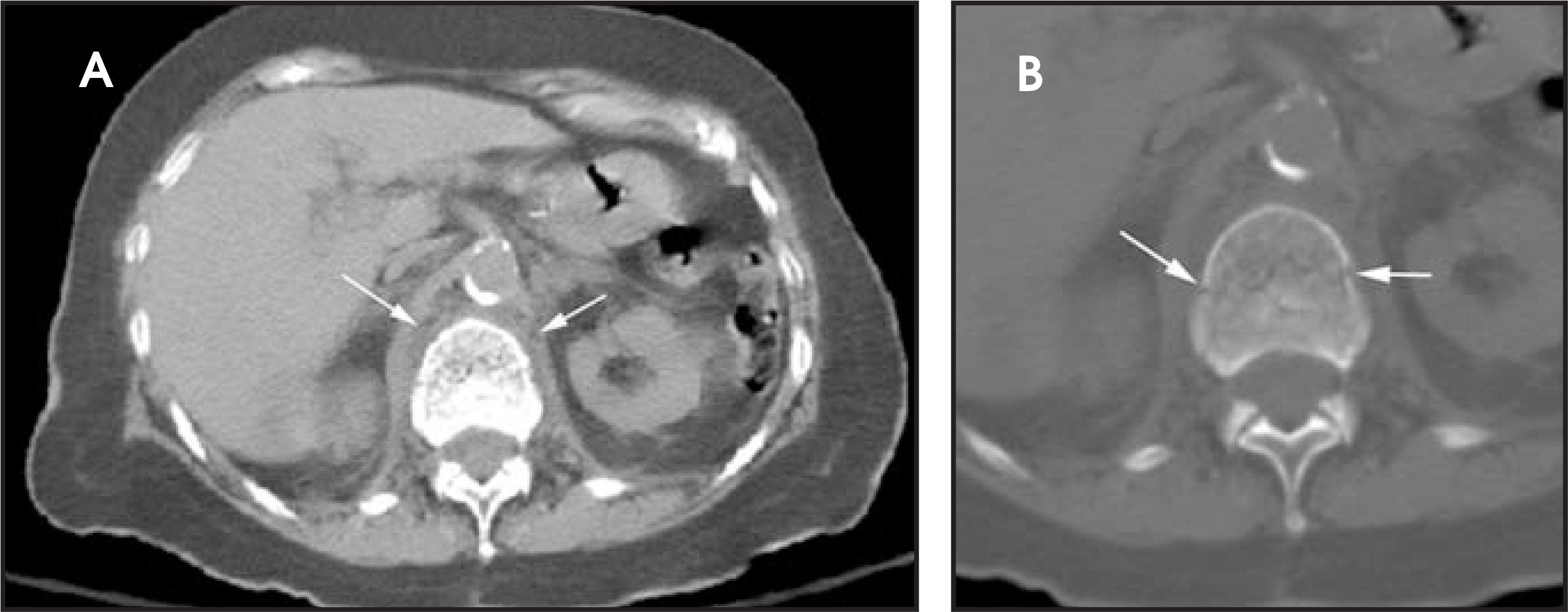
When MRI is contraindicated or cannot be tolerated by the patient, or when a neoplastic process is suspected and there is concern for the cortical integrity of the vertebral body, especially the posterior wall, a CT scan with multiplanar reformations can be performed (Figure 2). The CT scan is also helpful in identifying fracture lines, which may be a potential route for cement extravasation through the vertebral end-plate or elsewhere. Vertebral endplate fractures are a very common component of osteoporotic vertebral compression fractures and mayaccount for the increased rates of intradiscal cement extravasation that have been reported in the literature.11 Like plain radiographs, CT may also not be able to identify an acute fracture. Radiologists should always examine the spine in bone window settings in patients who undergo chest or abdomen CT examinations for unexplained symptoms that may be related to spine pathology (Figure 3). Skeletal scintigraphy can be used to identify acute or subacute vertebral compression fractures. These present as foci of increased uptake on the static images (Figure 1). Skeletal scintigraphy can be helpful in the evaluation of patients with suspected underlying malignancy.
A fluoroscopic study can be extremely useful in the evaluation of patients with suspected painful vertebral compression fractures. This author evaluates all of his patients with fluoroscopy as part of his initial consultation in order to determine if they meet the selection criteria for a vertebral augmentation procedure. The patient is placed in the lateral decubitus position; the spinous processes of the thoracic and lumbar spine as well as the sacral ala are palpated. Sites of pain provocation are subsequently examined under fluoroscopy (Figure 1). The patient is then placed in the prone position, and the examination is repeated. In general, if there is pain provocation at the level of the patient’s vertebral compression fracture, then that patient is a likely candidate for vertebral augmentation. Fluoroscopic evaluation is extremely sensitive in identifying painful vertebral compression fractures. The vertebral compression deformity can also be further evaluated in terms of morphology, height loss, presence or absence of cleft, location in the vertebral column, and size of pedicles. The visibility of the bony landmarks can also be quickly assessed in patients with poor bone mineralization and/or large body habitus. Lastly, fluoroscopy is able to dynamically evaluate patients with fracture instability associated with endplate motion, a phenomena that is sometimes seen in the thoracic spine and is related to respiratory motion. A couple of specific situations may confound this clinical fluoroscopic evaluation. Patients who have recently taken analgesics may not complain of pain. In this situation, the examination can be repeated when the analgesics are withheld for a brief period of time. Lastly, the examination may be difficult in patients suffering from dementia, but careful evaluation in this clinical setting usually identifies the symptomatic fracture.
Indications and contraindications
Vertebral augmentation procedures such as vertebroplasty or kyphoplasty are indicated for the treatment of pain related to vertebral compression fractures associated with osteoporosis, osteonecrosis, or osteolytic tumor infiltration (eg, multiple myeloma, metastasis). Patients with symptomatic sacral insufficiency or pathologic fractures may also be candidates for vertebral augmentation (sacroplasty) of the sacrumor coccyx (coccygeoplasty).12,13 These invasive spine procedures are contraindicated in patients who have uncorrected coagulopathy or preexisting spine or systemic infection, or in patients presenting with acute neurologic deficits related to the fracture. In the United States, these procedures are currently not indicated for the treatment of nonpathologic, traumatic vertebral fractures in young, non-osteoporotic patients.
Patient preparation
Vertebroplasty and kyphoplasty share many similar features, yet do have some significant differences. Both are invasive procedures and require that the patient receive nothing by mouth for at least 8 hours prior to the procedure. Laboratory parameters that are often analyzed prior to the procedure include hematologic, coagulation, and renal profiles. Informed consent is obtained prior to the procedure. The major risks of both procedures are extremely rare and well under 1% as compared with the potential benefit of significant pain relief in >90% of properly selected patients.
Technique
Vertebroplasty and kyphoplasty can be performed using either general intravenous anesthesia or intravenous sedation and analgesia. In specific situations in which patient comorbidities prevent the use of sedatives and analgesics, either procedure can be performed using local anesthetic agents. It is the hope of this author to dispense with the myth that kyphoplasty is always performed under general anesthesia. Each procedure can be performed on an outpatient or an inpatient basis, depending upon the clinical situation. Whether or not a patient is premedicated with antibiotics prior to the procedure is at the clinician’s discretion.
It is very important that all vertebral augmentation procedures are performed using strict aseptic technique. These procedures are performed with imaging guidance—usually a multidirectional single or biplane fluoroscope—but some operators prefer to perform them using CT or CT fluoroscopy. It is critical that the operator has access to high-quality imaging guidance so that key bony landmarks, such as the spinous process, pedicle, vertebral endplates, and posterior vertebral body wall are clearly visible, even in very osteopenic patients.
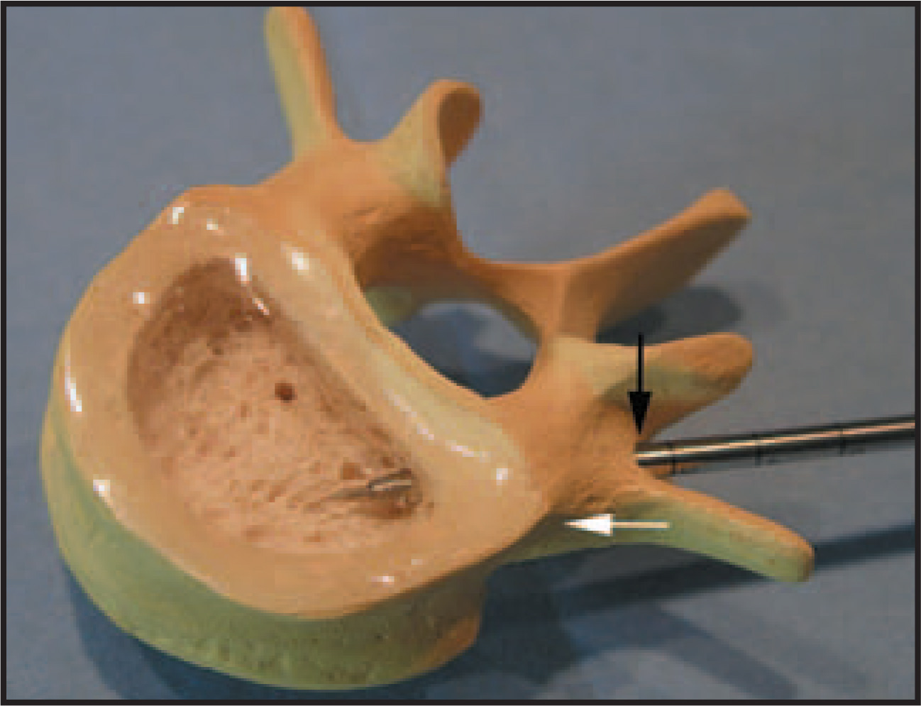
The patients are carefully placed in the prone position, and every attempt is made to bolster the patient so as to facilitate hyperextensionat the level of the vertebral compression fracture. This maneuver has been reported to predispose to height restoration even with vertebroplasty.14 Both vertebroplasty and kyphoplasty are performed using either a unilateral or bilateral approach, with the goal being to reach the anterior and paramedian aspect of the vertebral body. Either procedure can be performed via a transpedicular or parapedicular approach.The former approach is most commonly used, as it allows a relatively safe passage of the bone needle into the vertebral body (Figure 4).
Both procedures are performed with bone needles. Vertebroplasty is often performed with an 11- or 13-gauge bone needle, whereas kyphoplasty can be performed with a 10- or 8-gauge bone needle. When indicated, a bone biopsy can be performed using either procedure, as either needle system is amenable to the coaxial insertion of a biopsy cannula.
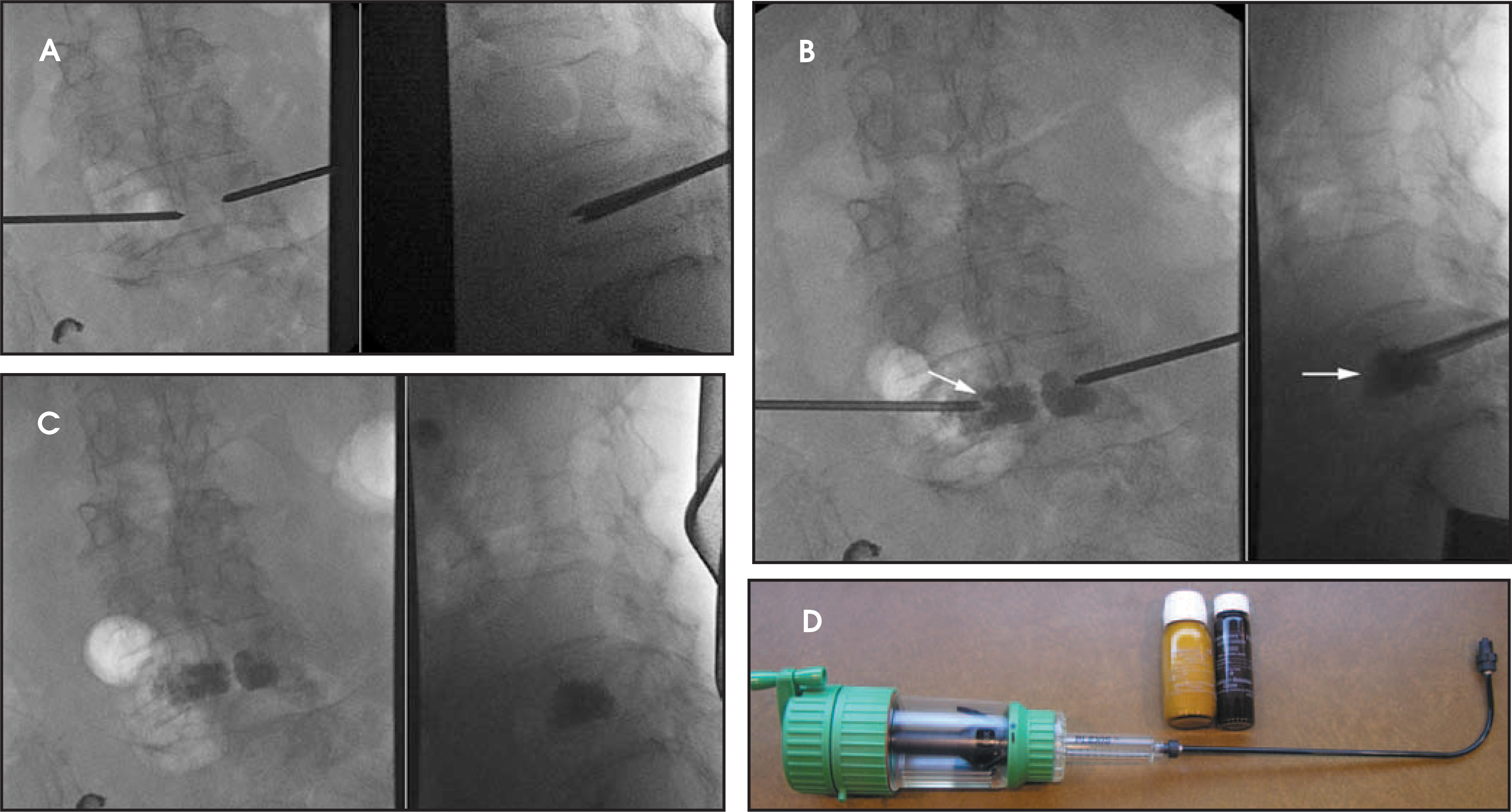
Vertebroplasty is performed in 2 steps: bone needle placement and cement injection (Figure 5).15-17 Kyphoplasty is performed in 3 steps: bone needle placement, temporary placement of an inflatable balloon tamp, and cement injection (Figure 6).2,18,19 Despite the additional step, kyphoplasty does not take significantly longer to perform than vertebroplasty. Many of the steps in the kyphoplasty procedure can be performed in parallel by an assistant operator, thereby reducing the procedure time. In our practice, a single-level vertebroplasty takes an average of 20 to 30 minutes, and a single-level kyphoplasty takes an average of 30 to 45 minutes to perform. The time factors are noted to emphasize procedural efficiency.
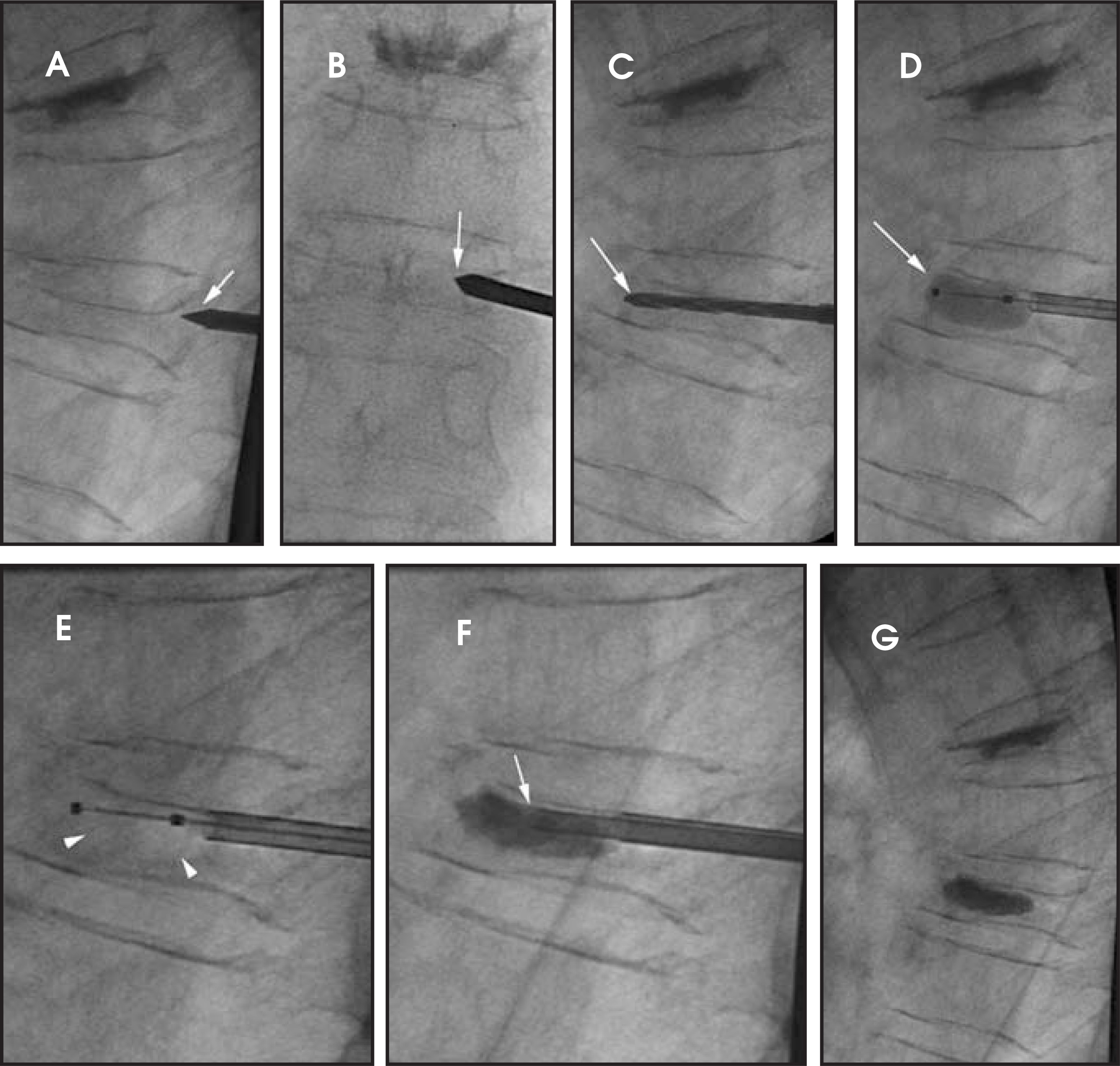
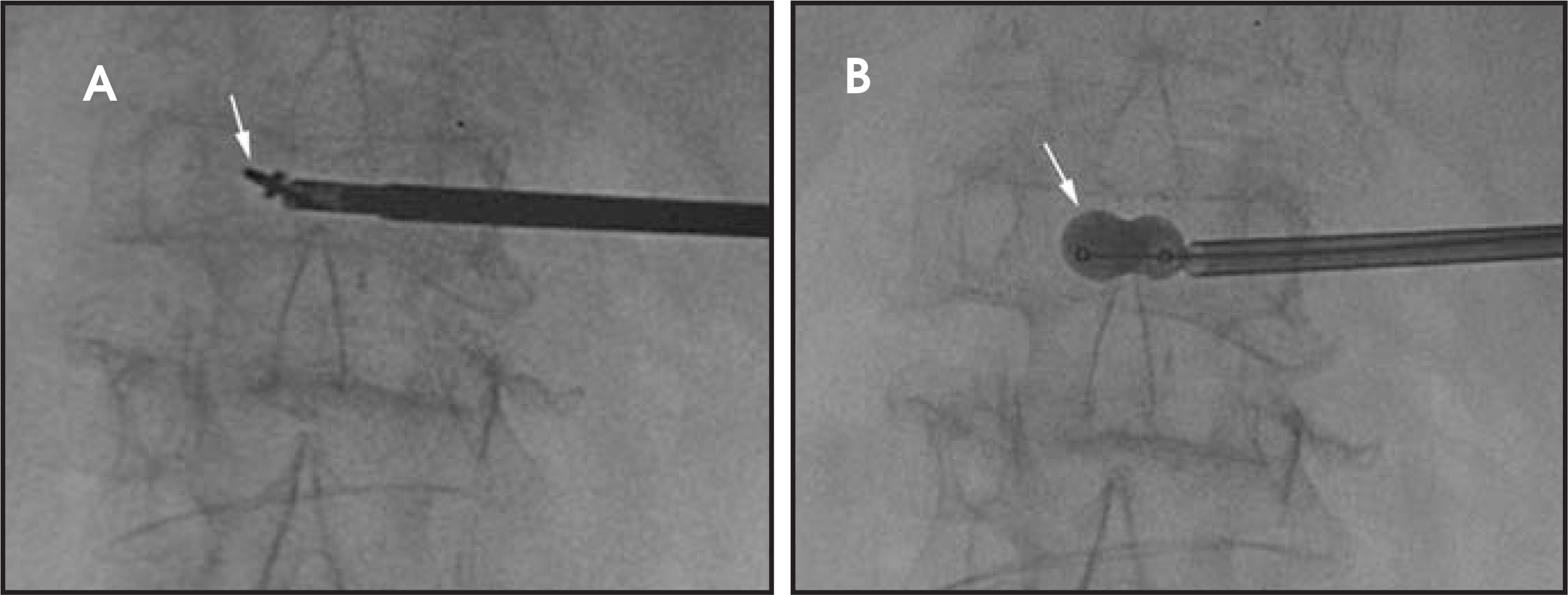
As each patient and each level are unique, treatments must be performed safely with an emphasis on meticulous needle placement techniques and imaging monitoring, regardless of the amount of time that is required to achieve this. Additional types of equipment are available with kyphoplasty that enable the creation of a working channel and working cavity; these present an opportunity for vertebral body reconstruction. A manual twist drill can be used to create a working channel and can help in advancing the bone needle. A bone curette can be introduced and used to remove foci of sclerotic bone or to facilitate the direction of balloon tamp inflation (Figure 7). The balloon tamps are currently available in 3 lengths (10-mm, 15-mm, and 20-mm) and 3 styles (standard multi-directional, unidirectional, and bidirectional). At present, the curette, 20-mm balloon tamp, and uni- and bidirectional tamps can be used only with the 8-gauge bone needle system. The balloon tamps are capable of sustaining high inflation pressures (300 or 400 psi depending on the size and style of the tamp). Once placed within the anterior and paramedian aspect of the vertebral body, the balloon tamp is gradually inflated, initially to 50 psi and subsequently in 25 psi increments, using a pressure manometer and a low osmolar nonionic iodine contrast agent. Endpoints for the termination of balloon tamp inflation include height restoration and close proximity of the balloon tamp to a cortical margin. Once the balloon tamp is deflated, a working cavity is created within the vertebral body that will serve as the principal site of cement deposition.
The majority of vertebral augmentation procedures use acrylic bone cement—polymethylmethacrylate that is impregnated with sterile barium sulfate (~30% wt/vol barium sulfate added to polymethylmethacrylate powder) for adequate radio-opacification.17 Several cement preparations are commercially available and offer reasonable working times (defined as the time from completion of cementmixing of the polymer powder and a liquid monomer to the time the cement has hardened and cannot be injected) with the cement product.
All cement injections should be performed with detailed imaging surveillance in order to avoid cement extravasation into critical areas such as the spinal canal or paraspinal veins. Cement injection with vertebroplasty is performed either with 1 mL syringes or with a commercially available cement delivery system (a device with a screw-in plunger that extrudes the cement from a reservoir through an extension tube). In kyphoplasty, the cement preparation is placed into bone filler devices, which can be coaxially introduced into the working cavity. A plunger is used to carefully extrude cement into the anterior aspect of the working cavity. In general, the larger size of the bone filler cannula allows the operator to use a thicker or more viscous cement preparation, as compared with the 11- or 13-gauge vertebroplasty cannula. In both procedures, the goal is to deposit cement within the vertebral body in order to stabilize the anterior column. It is not necessary, and, in fact, may be disadvantageous, to attempt to fill the entire vertebral body with bone cement. Biomechanical studies have shown that only a small volume of cement (in the range of 2.5 to 4.5 mL) is required in order to restorevertebral body strength.17 The endpoints for cement injection include adequate filling of the anterior column portion of the involved vertebral body, cement entering the basivertebral venous plexus, or cement extending beyond a vertebral body cortical margin in any direction.
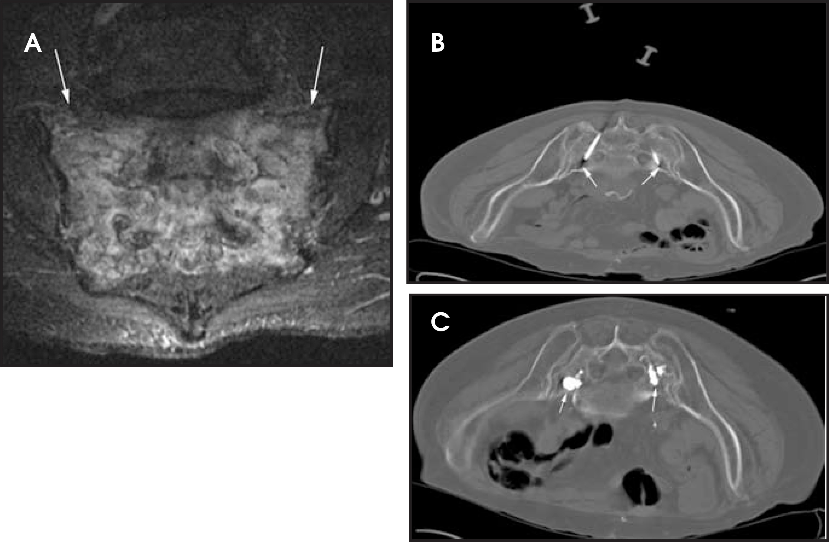
Vertebroplasty and kyphoplasty each have advantages and disadvantages. Vertebroplasty uses smaller-gauge bone needles and can be used to quickly treat a patient whose medical condition may warrant a treatment with the shortest procedure time. Vertebroplasty can be used throughout the entire spinal axis, including the cervical spine, where the first vertebroplasty was performed via a transoral approach.1,2,13 Sacroplasty entails the deposition of bone cement within sacral insufficiency fractures that often involve the sacral alae (Figure 8). Small vertebrae and small pedicles within the upper thoracic spine can be treated with this procedure. Patients with acute vertebral compression fractures with minimal height loss are also candidates for vertebroplasty.
It is challenging to control cement injection with vertebroplasty. Care must be taken to avoid or minimize cement extravasation. The cement injection will tend to follow a path of least resistance and will go along fracture planes. It is not uncommon for the fracture planes to extend to the vertebral endplate, hence this phenomenon may account for the frequent reports of intradiscal cement.11 Minimizing intradiscal cement extravasation is important, as there is some evidence that suggests a relationship between cement extravasation and new fractures at adjacentlevels.20,21 The reported complications for vertebroplasty and kyphoplasty include bleeding, infection, neural injury due to needle placement or cement extravasation (including radiculopathy and paralysis), fractures (ribs, sternum, other vertebrae) due to mishandling of fragile osteoporotic patients or altered biomechanics of a treated vertebra, pulmonary cement embolism due to venous extravasation of cement, severe idiosyncratic reactions to the bone cement, and death.4 Fortunately, major complications are extremely rare and, as with many procedures, tend to occur less frequently in the hands of experienced operators. Predisposition to new vertebral fractures at adjacent vertebral body levels is a potential complication of all vertebral augmentation procedures. Retrospective studies that have addressed the rates of subsequent vertebral fractures show a variable incidence of 12% to 52% at 1-year follow-up.22 This remains a difficult and controversial topic to analyze, as it is difficult to control for the natural history of patients with osteoporosis, whose fracture risk significantly increases following their first fracture event, and where the fracture site tends to cluster at the thoracolumbar junction, a known level of increased loading and biomechanical stress.4Furthermore, it has been observed that the subsequent fracture rate is greater in patients with steroid-related osteoporosis, and some of the retrospective studies do not account for this cohort nor do they stratify their patients according to bone mineral density.23
Kyphoplasty is utilized at the thoracic and lumbar spine levels. Acute and subacute vertebral compression fractures with height loss can usually be treated with kyphoplasty. The larger-gauge system employed in the kyphoplasty procedure enables the use of multiple tools and devices for the purposes of vertebral body augmentation (Figure 7). This instrumentation does add incremental cost to the procedure. It might be difficult, if not impossible, to use these instruments via a transpedicular route in the upper thoracic spine and in patients with small pedicles.
The potential to reconstruct the vertebral body is a desirable endpoint for any augmentative procedure. The opportunity to restore the height of a compressed vertebra is possible with kyphoplasty.19,24,25 Acute and subacute fractures, within 6 months of fracture occurrence, have the greatest likelihood of being reduced with kyphoplasty.26 Height restoration has also been reported by a few authors using the vertebroplasty procedure.14 Since one of the objectives of kyphoplasty is height restoration, the procedure can be particularly helpful at the thoracolumbar junction, where height loss is often associated with kyphosis and a wedge deformity of the fractured vertebra. Height restoration improves the alignment in this location with a favorable impact on spine biomechanics. The difficulty in evaluating the scientific literature on height restoration is that different measurement techniques have been utilized, making it difficult to compare outcomes.27 Similarly, the studies that show height restoration with vertebroplasty do not provide a detailed description of their hyperextension and bolstering techniques, so that it is notpossible to reproduce this outcome in other procedure labs.14,27,28 Studies on cadaveric vertebral bodies, however, do show some evidence of height restoration, which was seen to a greater extent following kyphoplasty.29,30
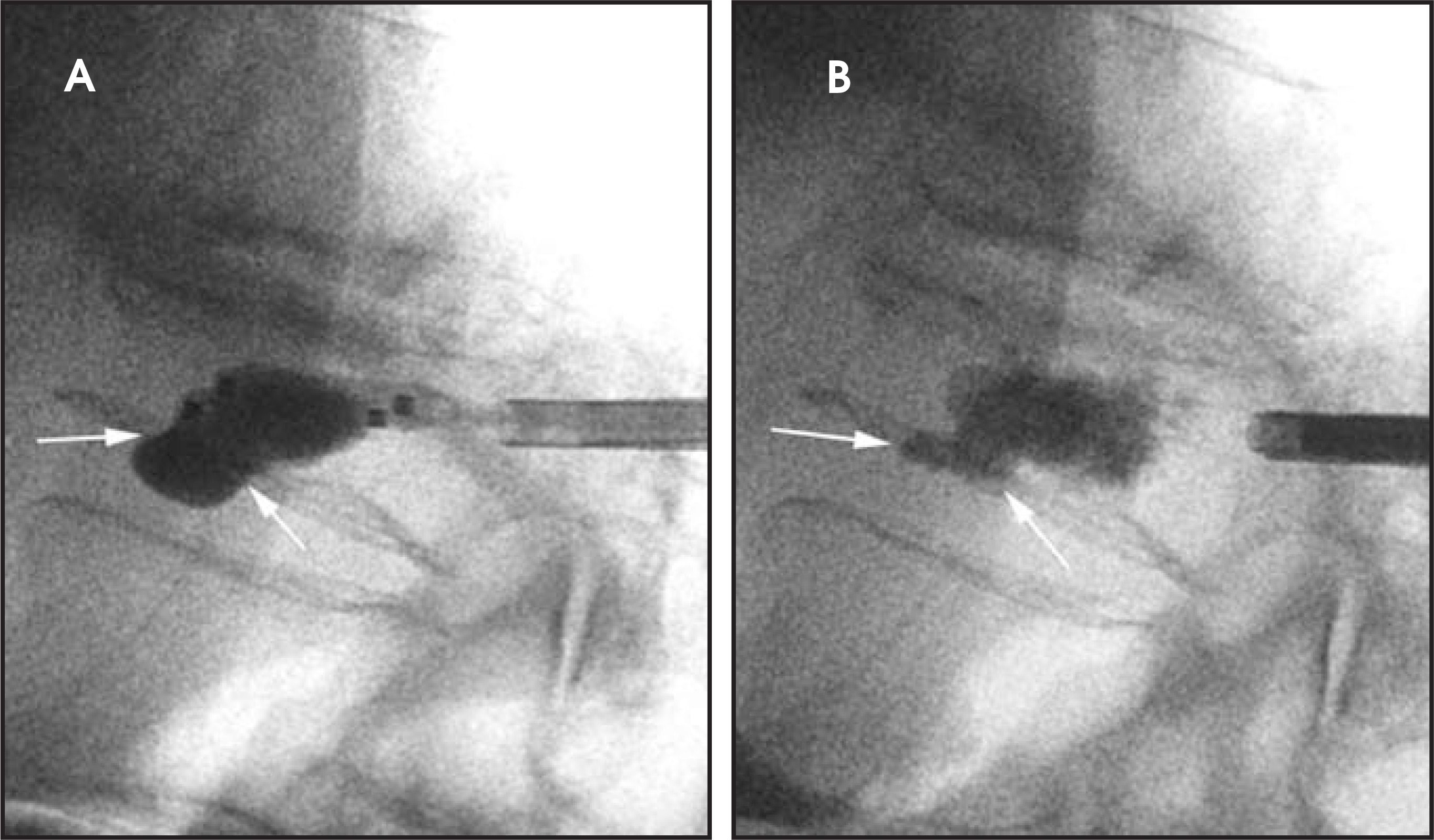
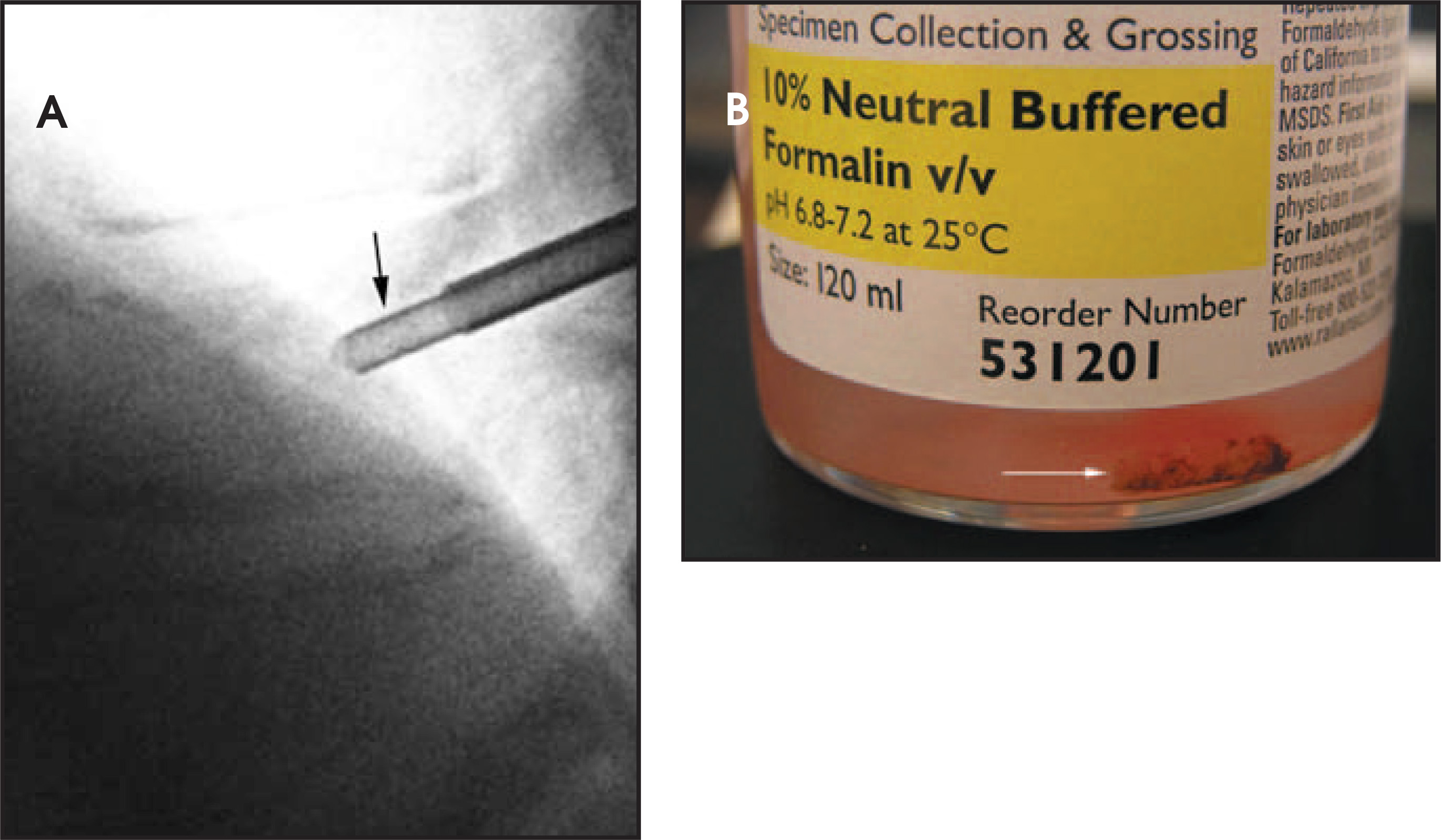
The vertebral endplate is often damaged in a significant number of vertebral body compression fractures. This is seen either directly with a vascular necrosis that involves the endplate or as the sequelae of an osteoporotic compression fracture. The damaged endplate may take on an angled configuration that is associated with a kyphotic deformity. Correction of this endplate deformity with height restoration is possible with balloon tamp inflation. This can help to reduce the kyphotic deformity that is often observed at the level of the fracture. Endplate defects are often seen in association with vertebral compression fractures. These defects are essentially fractures in the endplate. Endplate defects can potentially generate pain as the disc impinges on the damaged endplate during motion; these defects are also a potential site of cement extravasation due to compromise of this barrier. Every attempt should be made to keep cement within the vertebral body. Controlled cement delivery is readily achievable with the kyphoplasty procedure by creating a working cavity for the initial deposition of thick cement. The use of bone filler devices enables the application of thicker cement that is less prone to extend beyond the vertebral body margins. A smaller-gauge version of these bone filler devices is now available for coaxial use with 10.5-gauge bone needles that are used with vertebroplasty. Balloon tamp inflation often identifies large endplate defects; these defects can be a site for cement leak but can then be carefully sealed with thicker consistency cement (Figure 9). Another advantage in kyphoplasty is the opportunity for a greater specimen yield with the larger biopsy cannula when performing a biopsy (Figure 10).
Other vertebral augmentation techniques
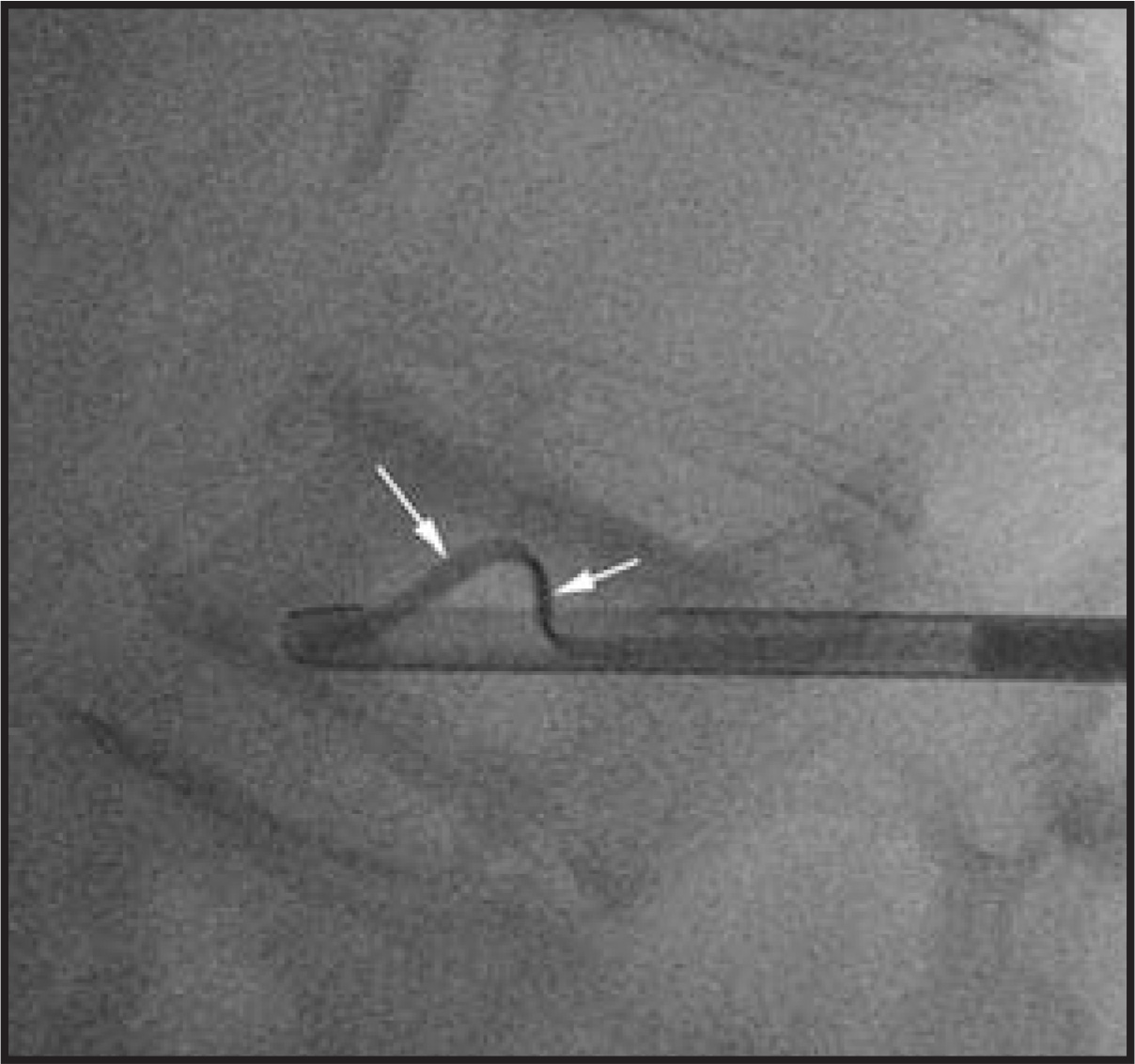
Other tools and percutaneous techniques have recently been developed to treat vertebral compression fractures. A coaxial needle systemwith a side port and an arc-shaped insert that protrudes for a variable distance beyond the needle margin can be used to facilitate the creation of a working cavity within the vertebral body (Figure 11). Although this tool remodels the center of the vertebral body, it does notsignificantly alter or reconstruct the cortical margins. A relatively new technique entails the sequential stacking of special PEEK wafers within the vertebral body in order to reinforce the vertebral body and provide height restoration. This procedure is performed using a unilateral parapedicular approach, as the insertion cannula is too large to enter the pedicle. A small amount of acrylic bone cement is then injected anterior and posterior to the implanted wafer stack (Figure 12). Other techniques have been used in an attempt to restore height to a compressed vertebra. One such modification entails the transpedicular placement of bone needles into the vertebral bodies that are located above and below the compressed vertebra.31 During cement injection, the operator and his/her assistants will push on the stabilizing needles in order to hyperextend the spine segment at the fracture site in an attempt to maximize height restoration. In this procedure, acrylicbone cement is injected not only into the compressed vertebra but also into the adjacent vertebrae.
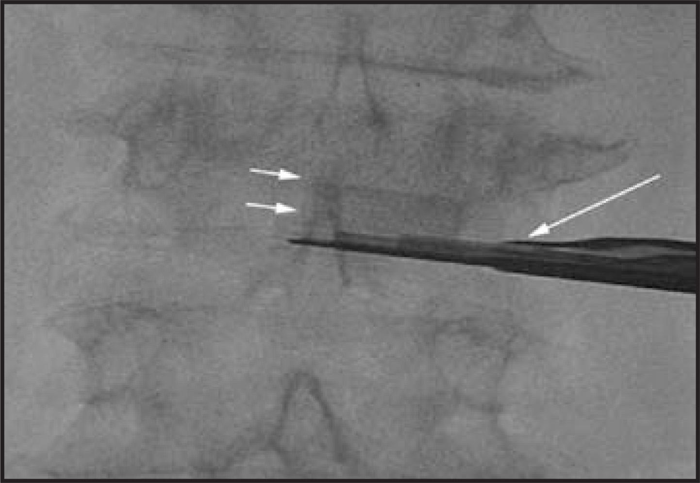
In addition to tool innovations and technique modifications, acrylic bone cement modifications and injectable agents other than acrylic bone cements have been developed for vertebral augmentation.32 A hydraulic injection system has been devised for the injection of thicker acrylic bone cement with the objective of controlling cement delivery. A different cement preparation consists of acrylic cement in conjunction with a ceramic agent that requires an instantaneous mixing of 2 agents from 2 syringes that are connected to a single injection chamber. The mixing of these 2 agents within the injection chamber and tube forms a composite cement that can be delivered in controlled aliquots, as only what is mixed is what is delivered into the bone needle.
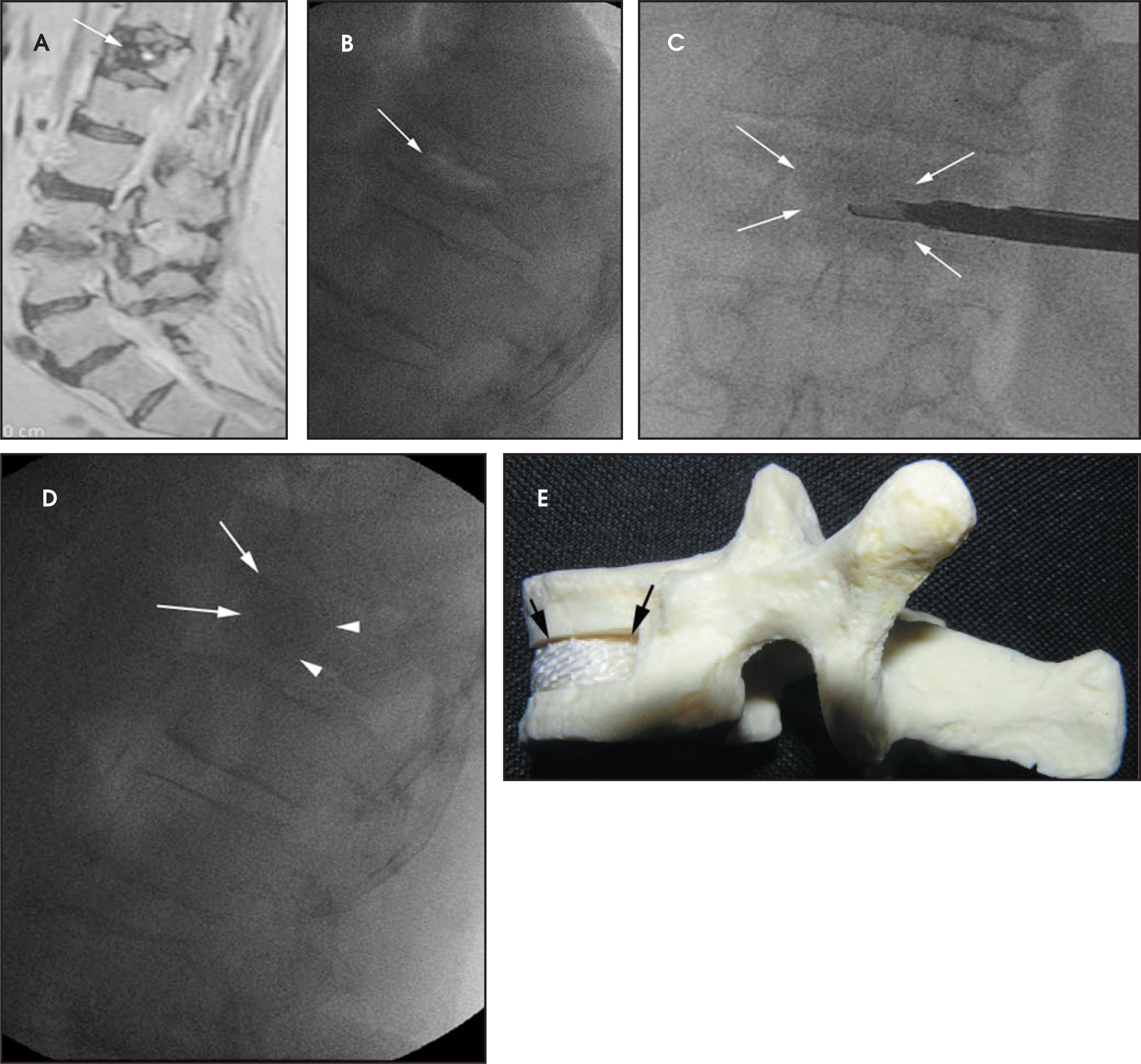
Previously, several attempts to develop and use biologic materials instead of acrylic bone cement for vertebral body augmentation have met with limited success. It is now possible to insert morselized particles of bone allograft into a compressed vertebra utilizing a percutaneous, unilateral, parapedicular approach with a moderate-sized coaxial cannula system.33 A shaper device creates a working cavity within the vertebral body, and a synthetic polymeric mesh sac is placed within this cavity. Bone allograft is sequentially tapped into the sac using bone fillertubes that are coaxially placed through the working cannula. This technology offers a few advantages, including controlled delivery,use of abiologic material, and vertebral body reconstruction with height restoration (Figure 13). This method, however, uses a large-caliber access portthat may not be suitable for use in the upper thoracic spine. Moreover, the durability of the bone material over time will require further study. Maximal pain relief reportedly takes a couple of weeks with this technique. Some operators are placing their patients on short-term parathyroid hormone (teraparatide) therapy in order to improve bone healing and bone formation at the treatment site.
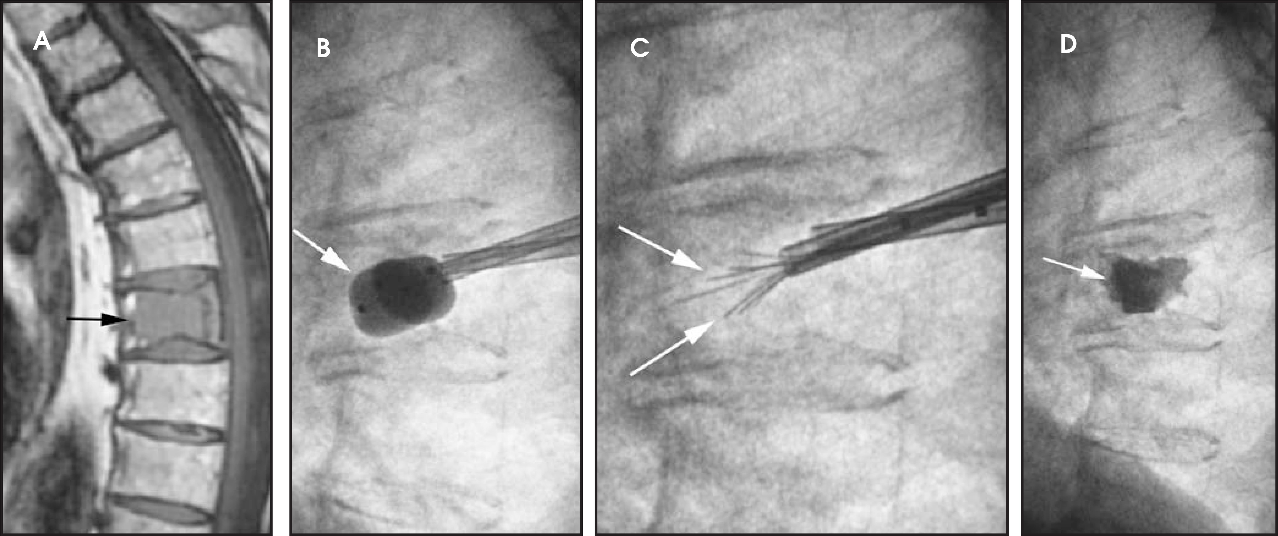
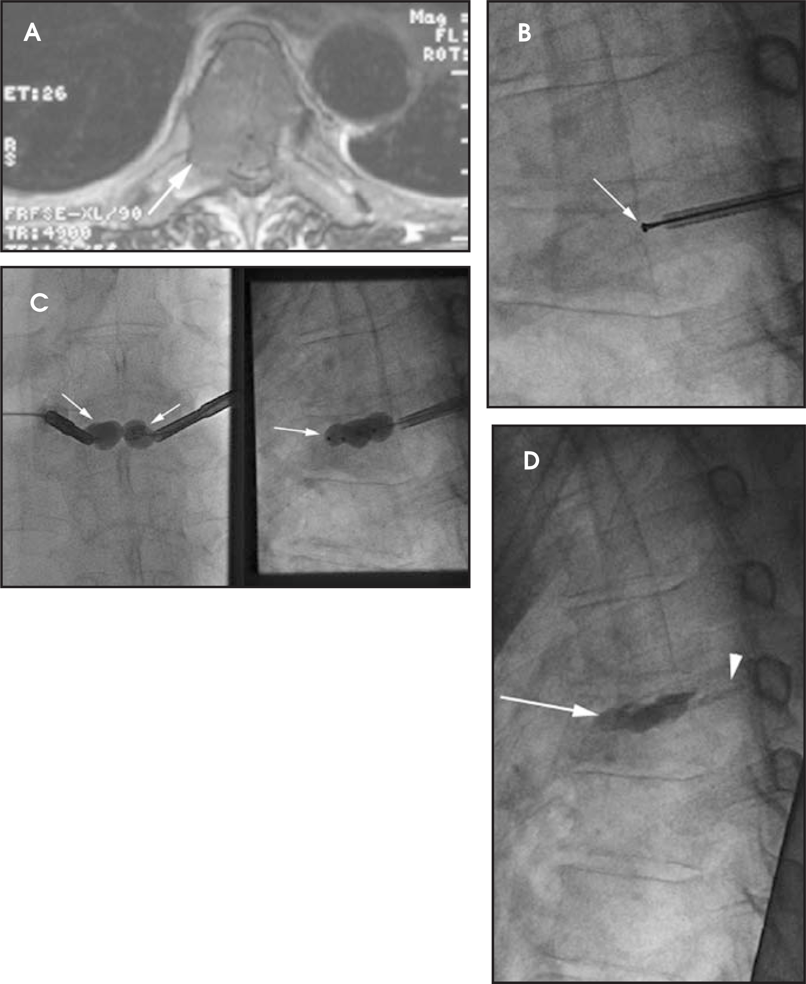
Vertebral augmentation is also used to treat fractures and vertebral lesions that occur with pathologic bone.34 The primary application has been in patients with myeloma, but metastatic lesions and primary vertebral body bone tumors have also been treated with vertebral augmentation. In terms of pain relief, the reported success rate in treating myelomatous and metastatic lesions of the spine is approximately 70%. There is, however, a potentially higher incidence of cement extravasation in these patients, so extreme care must be taken to avoid acomplication. Combined therapies have also been used to treat aggressive lesions of the spine, including the use of radiofrequency ablation or coblation therapies prior to the administration of acrylic bone cement (Figures 14 and 15). The objective of these hybrid therapiesis to reduce the tumor volume and facilitate cement injection for stabilization.35
Postprocedure Patient Management
Vertebral body reconstruction techniques are quickly evolving; nevertheless, vertebroplasty and kyphoplasty remain established procedures for the treatment of painful vertebral compression fractures. The care of the patient, however, does not stop once the procedure is completed. The patient’s underlying osteoporosis or neoplastic condition must be fully characterized and subsequently managed. Furthermore, it is not uncommon for a patient who experiences pain relief after vertebral augmentation to develop back pain that is related to one or more nonvertebrogenic pain generators in the spine. These patients perceive that their procedure has failed or that they have a new fracture.
For these reasons, it is our practice to see patients in follow-up at 3 weeks, 3 months, and 12 months after their procedure. Patients are assessed for degree of pain relief and are further evaluated for persistent pain or new severe pain. The patient is examined, under fluoroscopic guidance if necessary, and their outcome is clearly established. In certain instances, further imaging with MRI, CT, or skeletalscintigraphy may be necessary in order to assess for a potential procedural complication or another pain source such as a new fracture (Figure 16). Many of these fractures tend to occur within the first few months of treatment.36,37 This is often seen in osteoporotic patients who are suddenly pain-free and attempt to resume active lifestyles.
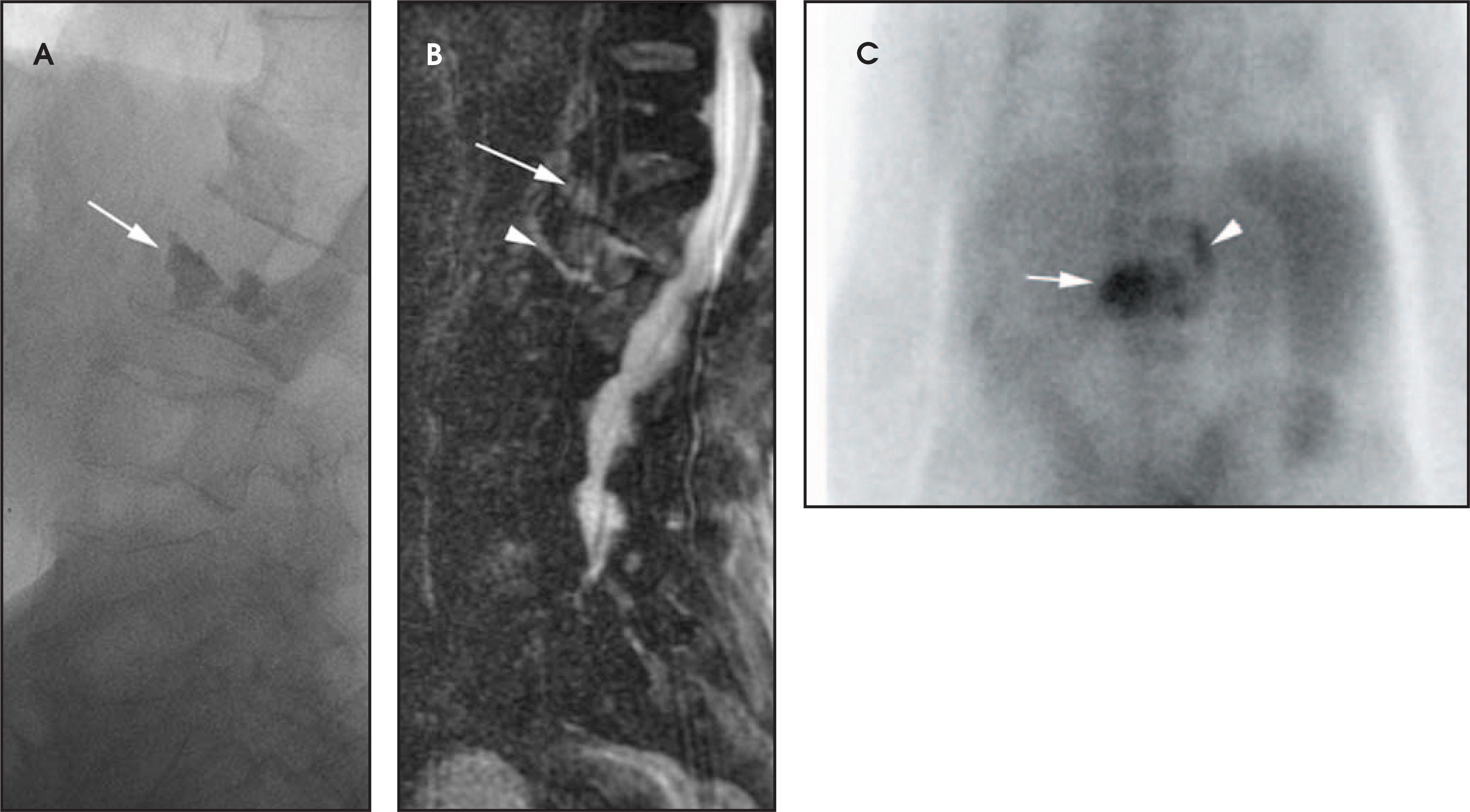
Radiologists should therefore be extremely aware of the postoperative appearance of the augmented spine, particularly on MRI. It is not uncommon to see residual abnormal signal within the vertebral body. This often represents the sequelae of healing and should not be interpreted as new or unresolved pathology. Furthermore, bone cement is hypointense on all sequences and should not be misinterpreted as gas or sclerotic bone. There may also be slight progression of height loss following vertebral augmentation. In many patients, their postprocedure back pain is often related to weakened paraspinal muscles that easily go into spasm, hence the rationale for physical therapy. Patients are also referred for physical therapy with an emphasis on spine rehabilitation. The latter management should focus on both anterior andposterior core muscle conditioning and improvement in balance and gait.
A large number of patients who present with painful osteoporotic vertebral compression fractures are not receiving adequate medical management for their condition. The need for active osteoporosis management in this patient population cannot be overemphasized.38,39 All of these patients should undergo bone density testing to properly assess their bone mineralization status. Patients with clinically proven osteoporosis should receive appropriate treatment for this condition. It has been shown that there is a significant reduction in fracture risk when osteoporosis management is instituted.40 Thus familiarization not only with vertebral body reconstruction techniques but also with osteoporosis as a disease entity will facilitate the appropriate evaluation and management of patients with fractures that affect the axial skeleton.
References
- Galibert P, Deramond H, Rosat P, Le Gars D. Preliminary note on the treatment of vertebral angioma by percutaneous acrylic vertebroplasty [in French]. Neurochirurgie. 1987;33:166-168.
- Wong W, Reiley M, Garfin S. Vertebroplasty/ kyphoplasty. J Women’s Imag. 2000;2:117-124.
- Mathis J, Ortiz A, Zoarski G. Vertebroplasty versus kyphoplasty: A comparison and contrast. AJNR Am J Neuroradiol. 2004;25:840-845.
- Jensen M, McGraw J, Cardella J, Hirsch J. Position statement on percutaneous vertebral augmentation: A consensus statement developed by the American Society ofInterventional and Therapeutic Neuroradiology, Society of Interventional Radiology, American Association of Neurological Surgeons/ Congress of Neurological Surgeons, and AmericanSociety of Spine Radiology. J Vasc Interv Radiol. 2007;18:325-330.
- Lyles K, Gold D, Shipp K, Pieper C. Osteoporotic vertebral fractures: Their association with impaired functional status. Am J Med. 1993;94:595-601.
- Heaney R. The natural history of vertebral osteoporosis. Is low bone mass an epiphenomenom?. Bone. 1992;13:S2-S26.
- Siminoski K, Jiang G, Adachi J. Accuracy of height loss during prospective monitoring for detection of incident vertebral fractures. Osteoporosis Int. 2005;16:403-410.
- Silverman S. The clinical consequences of vertebral compression fracture. Bone. 1992;13:S27-31.
- Lindsay R, Silverman S, Cooper C. Risk of new vertebral fracture in the year following a fracture. JAMA. 2001;285:320-323.
- Do H. Magnetic resonance imaging in the evaluation of patients for percutaneous vertebroplasty. Top Magn Reson Imaging. 2000;11:235-244.
- Jung J, Lee M, Ahn J. Leakage of polymethylmethacrylate in percutaneous vertebroplasty: Comparison of osteoporotic vertebral compression fractures with and without anintervertebral vacuum cleft. J Comput Assist Tomogr. 2006;30:501-506.
- Kortman K, Mathis J, Ortiz A, Mathis J, Deramond H, Belkoff S. Percutaneous Vertebroplasty and Kyphoplasty. 2006:197-209.
- Dean L, Syed M, Jan S. Coccygeoplasty: Treatment for fractures of the coccyx. J Vasc Interv Radiol. 2006;17:909-912.
- Teng M, Wei C, Wei L. Kyphosis correction and height restoration effects of percutaneous vertebroplasty. AJNR Am J Neuroradiol. 2003;24:1893-1900.
- Jensen M, Evans A, Mathis J. Percutaneous polymethylmethacrylate vertebroplasty in the treatment of osteoporotic vertebral compression fractures: Technical aspects. AJNR Am J Neuroradiol. 1997;18:1897-1904.
- Kallmes D, Jensen M. Percutaneous vertebroplasty. Radiology. 2003;229:27-36.
- Mathis J, Barr J, Belkoff S. Percutaneous vertebroplasty: A developing standard of care for vertebral compression fractures. AJNR Am J Neuroradiol. 2001;22:373-381.
- Garfin S, Yuan H, Reiley M. New technologies in spine: Kyphoplasty and vertebroplasty for the treatment of painful osteoporotic compression fractures. Spine. 2001;14:1511-1515.
- Lieberman I, Dudeney S, Reinhardt M, Bell G. Initial outcome and efficacy of “kyphoplasty” in the treatment of painful osteoporotic vertebral compression fractures. Spine Spine.
- Lin E, Ekholm S, Hiwatashi A, Westesson P. Vertebroplasty: Cement leakage into the disc increases the risk of new fracture of adjacent vertebral body. AJNR Am J Neuroradiol. 2004;25:175-180.
- Syed M, Patel N, Jan S. Intradiskal extravasation with low-volume cement filling in percutaneous vertebroplasty. AJNR Am J Neuroradiol. 2005;26:2397-2401.
- Grados F, Depriester C, Cayrolle G. Long-term observations of vetebral osteoporotic fractures treated by percutaneois vertebroplasty. Rheumatology. 2000;39:1410-1414.
- Harrop J, Prpa B, Reinhardt M, Lieberman I. Primary and secondary osteoporosis’ incidence of subsequent vertebral compression fractures after kyphoplasty. Spine. 2004;29:2120-2125.
- Theodorou D, Theodorou S, Duncan T. Percutaneous balloon kyphoplasty for the correction of spinal deformity in painful vertebral body compression fractures. Clin Imaging. 2002;26:1-5.
- Phillips F, Ho E, Campbell-Hupp M. Early radiographic and clinical results of balloon kyphoplasty for the treatment of osteoporotic vertebral compression fractures. Spine. 2003;28:2260-2267.
- Ortiz A, Buonocore B, Zoarski G. Height restoration following kyphoplasty for treatment of painful osteoporotoic vertebral compression fractures. J Women’s Imag. 2005;7:102-110.
- McKiernan F, Faciszewski T, Jensen R. Reporting height restoration in vertebral compression fractures. Spine. 2003;28:2517-2521.
- Hiwatashi A, Moritani T, Numaguchi Y, Westesson P. Vertebral height restoration following percutaneous vertebroplasty. AJNR Am J Neuroradiol. 2003;24:185-189.
- Hiwatashi A, Sidhu R, Lee R. Kyphoplasty versus vertebroplasty to increase vertebral body height: A cadaveric study. Radiology. 2005;237:1115-1119.
- Belkoff S, Mathis J, Fenton D. An ex vivo biomechanical evaluation of an inflatable bone tamp used in the treatment of compression fracture. Spine. 2001;26:151-156.
- Heini P, Orler R, Boszczyck B, Mathis J, Deramond H, Belkoff S. Percutaneous Vertebroplasty and Kyphoplasty. 2006:134-144.
- Lieberman I, Togawa D, Kayanja M. Vertebroplasty and kyphoplasty: Filler materials. Spine J. 2005;5:305S-316S.
- Chiu J, Stechison M. Percutaneous vertebral augmentation and reconstruction with an intravertebral mesh and morcelized bone graft. Surg Technol Int. 2005;14:287-96.
- Fourney D, Schomer D, Nader R. Percutaneous vertebroplasty and kyphoplasty for painful vertebral body fractures in cancer patients. J Neurosurg. 2003;98(1 suppl):21-30.
- Georgy B, Wong W. Plasma-mediated radiofrequency ablation assisted percutaneous cement injection for treating advanced malignant vertebral compression fractures. AJNR Am J Neuroradiol. 2007;28:700-705.
- Uppin A, Hirsch J, Centenera L. Occurence of new vetebral body fracture after percutaneous vertebroplasty in patients with osteoporosis. Radiology. 2003;226:119-124.
- Fribourg D, Tang C, Sra P. Incidence of subsequent vertebral fracture after kyphoplasty. Spine. 2004;29:2270-2277.
- Hooven F, Gehlbach S, Pekow P. Follow-up treatment for osteoporosis after fracture. Osteoporosis Int. 2005;16:296-301.
- Weigert J. A review of current therapeutic options for osteoporosis. J Women’s Imaging. 2004;6:57-63.
- Harris S, Watts N, Genant H. Effects of risedronate treatment on vertebral and nonvertebral fractures in women with postmenopausal osteoporosis: A randomized controlled trial. Vertebral Efficacy With Risedronate Therapy (VERT) Study Group. JAMA. 1999;282:1344-1352.
Citation
. Vertebral body reconstruction: Review and update on vertebroplasty and kyphoplasty. Applied Radiology. 2008;37(12):10-24. doi:10.37549/AR1668.